Triplett 1201 User Manual
Page 2
4. If fuse blows, remove meter from circuit under test. Replace fuse by
removing the rear battery cover (2 screws) to access fuse.
7-5 Measuring Resistance
7-5-1 Connect the black test lead to COM jack and red lead to VΩmA jack.
7-5-2 Set the rotary switch to the desired Ω range position.
7-5-3 Connect the test leads across the resistance under measurement.
7-5-4 Read the resistance on the LCD.
NOTE:
1. DO NOT APPLY VOLTAGE WHEN MEASURING RESISTANCE.
2. If “1” or “-1” is displayed, it indicates over range. This means that the test
leads are not making connection to the circuit, or the resistance exceeds
the measurement ability of the selected range. Select a higher range to
obtain a measurement.
3. When measuring resistances above 1MΩ, the meter may take a few
seconds for the reading to stabilize.
4. When checking in-circuit resistance, be sure the circuit under test has all
power removed and that all capacitors have been fully discharged
7-6 Measuring Temperature
7-6-1 Set the rotary switch to the °F range position.
7-6-2 The LCD will show the present temperature of the meter.
7-6-3 To use the K-type thermocouple probe, connect the black banana plug
of the probe into the
COM jack and the red banana plug to the VΩmA
jack.
7-6-4 The temperature of the thermocouple probe tip is displayed on the
LCD
7-6-5 The probe included with the meter can be used for measuring
temperature up to 482
°F. To accurately measure higher
temperatures, use a high temperature rated K-type probe.
NOTE:
1. Do not connect the thermocouple probe to a voltage source
7-7 Battery Testing
7-7-1 Connect the black test lead to COM jack and red lead to VΩmA jack.
7-7-2 Set the rotary switch to the proper “ ” or “ ” range position to
test either a 1.5V or 9V battery.
7-7-3 Connect test leads to the + and - terminals of the battery under test
7-7-4 The LCD displays the battery’s voltage at the rated test current.
7-8 Diode Testing
7-8-1 Connect the black test lead to COM jack and red lead to VΩmA jack.
7-8-2 Set the rotary switch to the “
” position.
7-8-3 Connect the red lead to the anode of the diode to be tested, and the
black lead to the cathode.
7-8-4 The diode’s forward voltage drop is displayed on the LCD.
NOTE:
1. The meter will display the approximate forward voltage drop of the diode.
2. If the leads are reversed or not connected, “1” (over range) should be
displayed
7-9 Continuity Testing
7-9-1 Connect the black test lead to COM jack and red lead to VΩmA jack.
7-9-2 Set the rotary switch to the “
” position.
7-9-3 Connect the test leads to the two points of the circuit under test.
7-9-4 If there is continuity (resistance is lower than approximately 50Ω)
the built-in beeper will sound and the red LED indicator above the
LCD will illuminate.
NOTE:
1. Do not attempt this measurement on energized circuits.
2. If the leads are reversed, not connected, or connected to a resistance
more than approximately 2000Ω, “1” (over range) should be displayed
8. Battery Replacement
8-1 If the battery voltage drops below proper operation range the “ “
symbol will appear on the LCD display and the battery should be
changed.
8-2 Before attempting to remove the rear cover to replace the battery, be
certain the test leads have been disconnected from the circuit to avoid
electrical shock hazard. Power off the meter and remove the test leads
from the banana jacks. To access the battery cabinet, remove the (2)
screws in the rear cover and lift the cover.
8-3 Replace the old battery with the same type battery (9V 6F22 or NEDA
1604).
8-4 Replace the rear cover of the meter and reinstall the (2) screws.
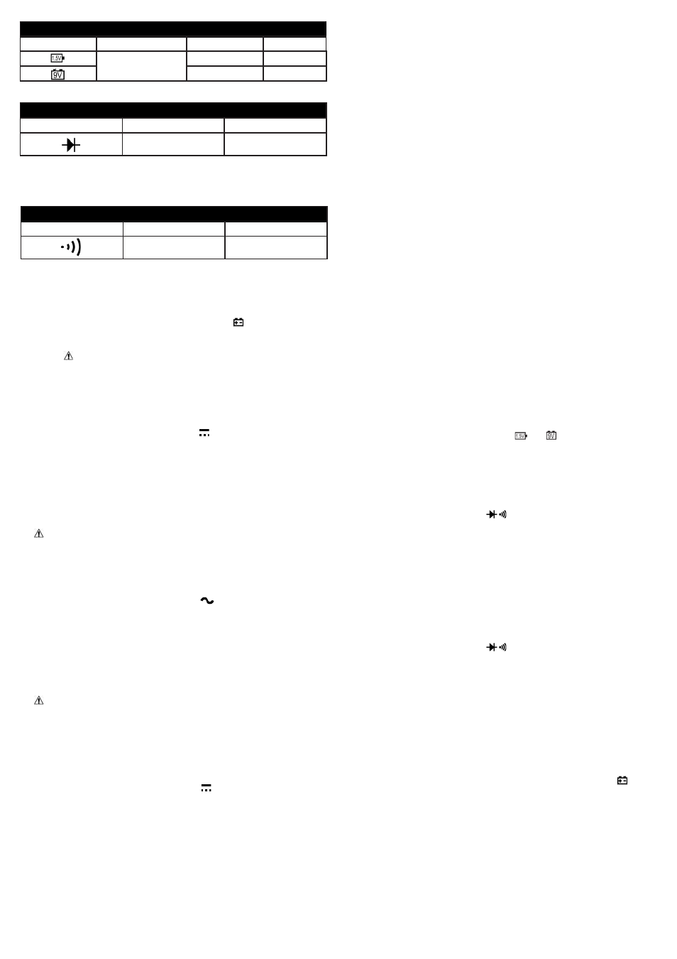
Continuity test
Range
Description
Function
0 to 2000Ω
Buzzer sounds if resis-
tance is less than 50Ω
Overload protection: 500V AC / DC
Open circuit voltage: Approximately 3V
7. Operating Instructions
7-1 Before Operation
7-1-1 Check battery. If the battery voltage is low, the symbol will appear
on the LCD display. Replace by removing the (2) screws in the rear
panel and lifting the battery cover up.
7-1-2 The near the input jacks warns of limitations in the input voltage
and current. DO NOT EXCEED THESE LIMITS.
7-1-3 The rotary switch should be positioned to the proper function and
measurement range BEFORE connecting the test leads to the circuit.
7-2 Measuring DC Voltage
7-2-1 Connect the black test lead to COM jack and red lead to VΩmA jack.
7-2-2 Set the rotary switch to the desired “V ” range position.
7-2-3 Observing polarity, connect test leads across the circuit component(s)
under measurement and read the voltage from the LCD.
NOTE:
1. When the quantity to be measured is unknown, set the rotary switch to its
highest DC voltage range before connecting the test leads to the circuit.
2. When only “1” or “-1” is displayed, it indicates “over range”. Either select
a higher measurement range or do not continue to measure.
3. Although the meter may measure voltages higher than 600V, it may
be damaged or pose a shock hazard or other injury to the user.
4. Use caution when measuring high voltages (>60V DC or >30V AC).
7-3 Measuring AC Voltage
7-3-1 Connect the black test lead to COM jack and red lead to VΩmA jack.
7-3-2 Set the rotary switch to the desired “V
” range position.
7-3-3 Observing polarity, connect test leads across the circuit component(s)
under measurement and read the voltage from the LCD.
NOTE:
1. When the quantity to be measured is unknown, set the rotary switch to its
highest AC voltage range before connecting the test leads to the circuit.
2. When only “1” or “-1” is displayed, it indicates “over range”. Either select
a higher measurement range or do not continue to measure.
3. Although the meter may measure voltages higher than 600V, it may
be damaged or pose a shock hazard or other injury to the user.
4. Use caution when measuring high voltages (>60V DC or >30V AC).
7-4 Measuring DC Current
7-4-1 Connect the black test lead to COM jack and red lead to the VΩmA
jack for a maximum 200mA current. For a maximum 10A current,
move the red lead to the
10A jack.
7-4-2 Set the rotary switch to the desired “A ” range position.
7-4-3 Observing polarity, connect test leads in series with the load under
measurement.
7-4-4 Read current from the LCD.
NOTE:
1. When the quantity to be measured is unknown, set the rotary switch to
its highest position (200mA or 10A depending on the jack used) before
connecting test leads to the circuit.
2. When only “1” or “-1” is displayed, it indicates “over range”. Either select
a higher measurement range or do not continue to measure.
3. Current above 200mA on the VΩmA jack will blow the fuse. The 10A jack
is not fused. Do not apply more than 10A. Do not apply 10A for longer
than 10 seconds. Allow a 15 minute cooldown.
Battery test
Range
Accuracy
Load current
Resolution
Approx. 50mA
Approx. 10mA
1mV
10mV
±(5.0% of rdg+ 5 digits)
Overload protection: Fast Acting 200mA / 500V fuse
Diode test
Range
Description
Resolution
Forward voltage drop of
diode
1mV
Overload protection: 500V AC / DC
Test Current: Approximately 1mA
Open Circuit Voltage: Approximately 3V