Tri Tool 212B Miter Mandrel User Manual
Page 12
12
TRI TOOL INC.
92-0449 : Orig. 930630
NOTE:
NOTE:
The first adjustment to be made after mounting is always the angular offset.
Changing the angular offset will always change the parallel offset, but
changing the parallel offset will not change the angular offset.
To move the Mandrel Shaft in a given direction, one (1) or two (2) Angular Offset
Adjustment Screws must be loosened enough to allow the amount of movement
anticipated in the opposite direction. Then the Angular Offset Adjustment Screws
directly across must be retightened to draw the Mandrel Shaft in the desired direc-
tion.
Never exceed 40 ft-lbs. (54 N m) of torque on the angular offset Adjustment
Screws.
Repeat the indicating procedure and the angular offset procedure as many times as
necessary to achieve the accuracy desired.
Evenly torque all four (4) Angular Offset Adjustment Screws.
Now the parallel offset adjustment may be made.
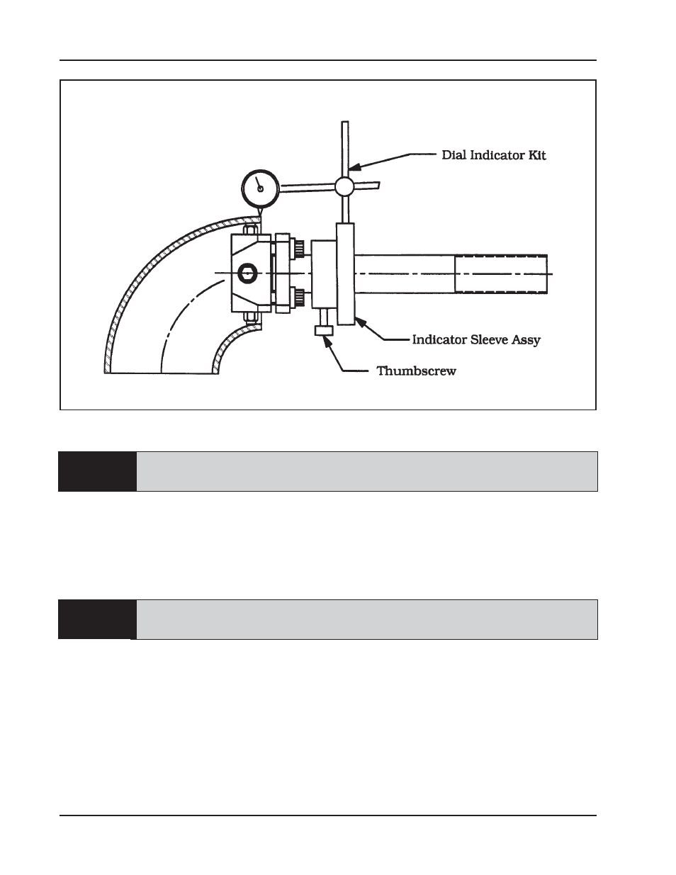
Mounting the Indicator Kit on the Mandrel
- 204B Cutting Head (9 pages)
- 204B Cutting Head (10 pages)
- 204B Cutting Head (9 pages)
- 212B Single Point Spring Hanger Assembly (8 pages)
- 204B Cutting Head (13 pages)
- 204B Cutting Head (36 pages)
- 204B Cutting Head (17 pages)
- 201BA Beveler (36 pages)
- 204B Elbow Mandrel (16 pages)
- 204B Beveler (45 pages)
- 204B Flange Facer (21 pages)
- 206B Elbow Mandrel (17 pages)
- 206B Flange Facer (22 pages)
- 206B Beveler (45 pages)
- 212B ID Tracking Module (17 pages)
- 206B Miter Mandrel (16 pages)
- 206B Sleeve Mandrel (13 pages)
- 208B Elbow Mandrel (20 pages)
- 208B ID Tracking Module (18 pages)
- 208B Miter Mandrel (20 pages)
- 208B Flange Facer (28 pages)
- 208B Sleeve Mandrel (15 pages)
- 212B Elbow Mandrel (16 pages)
- 214B Beveler Single Point Flange Facer (41 pages)
- 212B Flange Facer (22 pages)
- 212B Single Point Hydraulic Motor Assembly (9 pages)
- 212B Single Point Flange Facer Miter Mandrel (28 pages)
- 212B Sleeve Mandrel (12 pages)
- 214B Elbow Mandrel (20 pages)
- 214B Flange Facer (23 pages)
- 214B ID Track Module (19 pages)
- 214B Miter Mandrel Head Kit (22 pages)
- 214B Sleeve Mandrel (13 pages)
- 236B ID Tracking Module (23 pages)
- 224B Miter Mandrel (27 pages)
- 224B Single Point (30 pages)
- 230B Beveler Flange Facer (16 pages)
- 230B ID Tracking Module (15 pages)
- 230B Lifting Frame (19 pages)
- 236B Miter Mandrel (25 pages)
- 301SP Tube Squaring (35 pages)
- 236B Single Point (32 pages)
- 302 Tube Squaring Micro Feed Assembly (11 pages)
- 302 Tube Squaring (31 pages)