Snotrace, Terminating the heating cable, Installation on stairs – Thermon KSR User Manual
Page 3
SnoTrace
TM
KSR
TM
6. Cable layout must insure that both ends of cable end in the
junction box (see example 1). If there is not enough cable
to do so following the layout drawing, adjust the layout
by shortening every other cable towards the center from
the corners and ends slightly (see example 2). Contact
Thermon prior to completion of installation should there
be any discrepancies between the layout drawings and
actual field conditions.
Example 1
Designed Routing
Example 2
In Field, Solution
7. Where expansion joints must be crossed, KSR-EJK expan-
sion joint kits are to be installed as shown below.
8. Attach cable with nylon tie straps on approximately 12"
centers such that installed cable will be between 2" and 3"
below the snow melting surface of the concrete.
DO NOT Use metal wire to secure heating cable
to rebar or steel mesh - electrical
hazard and short circuits could result!
Terminating the Heating Cable . . .
1. Upon completion of the cable layout recheck the spacing
and ensure agreement with the specific project layout
drawings. Check circuit length to insure length does not
exceed maximum length provided in Design Guide.
2. Terminate the ends of the snow melting cable using a
KSR-CFK circuit fabrication kit and the accompanying
instruction sheets.
2
KSR
KSR
2"- 3"
KSR
KSR
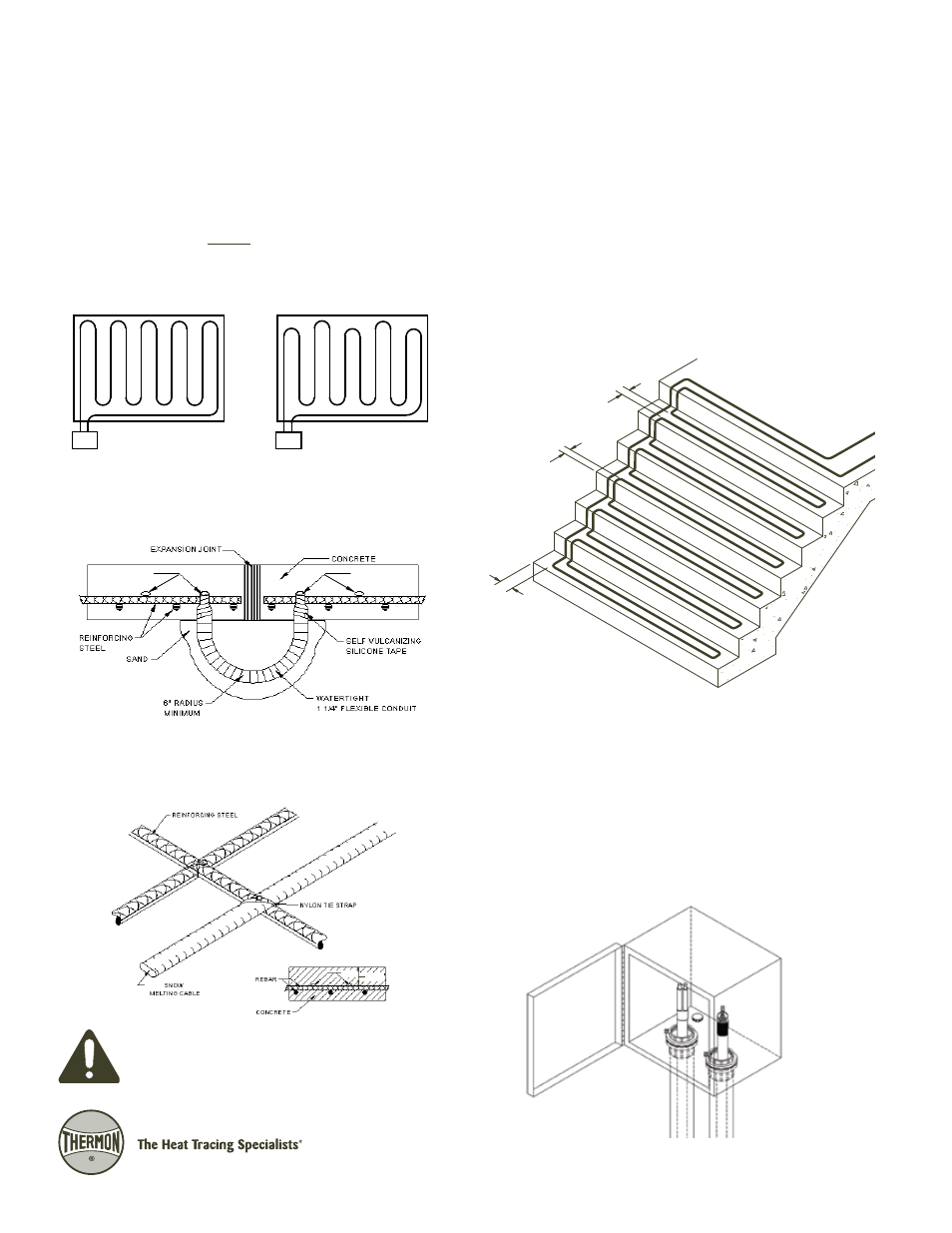
2" (TYP.)
6" (TYP.)
4" (TYP.)
FROM EDGE
CABLE SPACING APPROX.
FROM FRONT OF
FINISHED TREAD
1. Cable to be attached to rebar or wire mesh with nylon tie
straps on approximately 18" centers such that installed
cable will be between 2-1/2" to 3" below the snow melt-
ing surface of the stairs.
2. If dual pour used for construction of stairs, top cap must
be minimum 2-1/2" thick. Corner of base pour must be
removed where cable transitions from horizontal to vertical
placement.
Installation on Stairs . . .