Snotrace ™ ksr, Installation procedures – Thermon KSR User Manual
Page 2
Refer to the “SnoTrace KSR Cable Testing Report” for required
recording of test data and circuit information.
Upon Receiving Cable . . .
1. Upon receiving heating cable, check to make sure the
proper type and output have been received. All cables are
printed on the outer jacket with part number, voltage rating
and watt output.
2. Visually inspect cable for any damage incurred during ship-
ment. The heating cable should be tested to ensure electri-
cal integrity with at least a 500 Vdc megohmmeter (meg-
ger) between the heating cable bus wires and the heating
cable metallic braid. IEEE 515.1 recommends that the test
voltage for polymer insulated heating cables be 2500 Vdc.
Minimum resistance should be 20 megohms. (Record 1 on
Cable Testing Report.)
4. Route heater cable ends through rigid galvanized conduit
into power/end termination box and temporarily fix both
ends of the cable in the box. Leave at least 6” for termina-
tions later.
5. Lay out cable on top of rebar in a serpentine fashion
beginning at the power box on centerline spacing as
specified on project drawings. Bend cable in smooth arcs
having a radius of no less than 2”. Avoid crossing expan-
sion joints in the cable layout.
Installation of Cable . . .
1. Snow melting cable systems must be installed in accor-
dance with the National Electrical Code, Canadian Electrical
Code or any other applicable code. Review the require-
ments prior to installation.
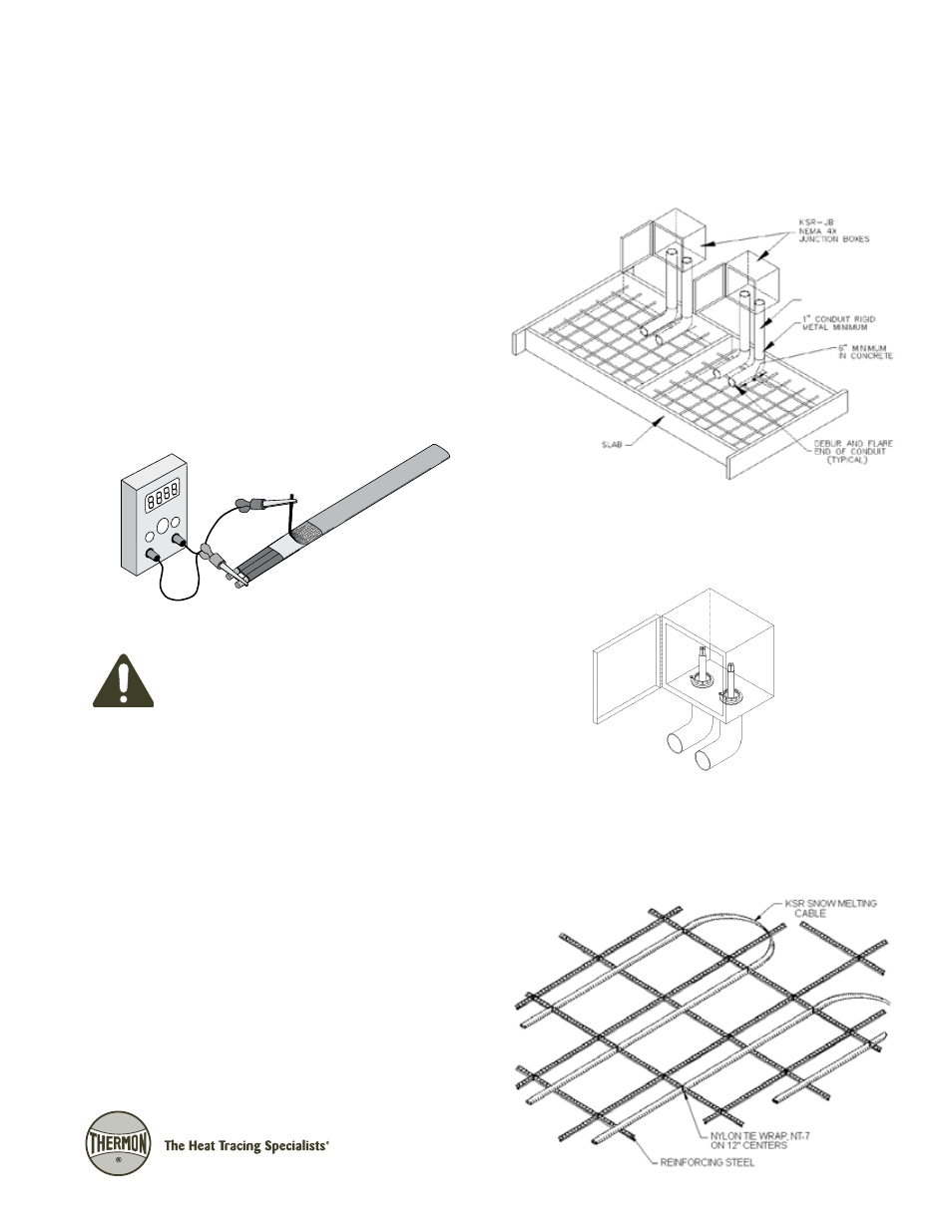
2. Thermon recommends the heating cable junction boxes be
placed adjacent to the edge of the slab, approximately 12”
above grade, as shown on the illustration top right. If this is
not feasible due to physical constraints of the installation,
the cable can be routed through 1” minimum rigid metal
conduit from the slab to the junction box. Only one heat-
ing cable per each conduit; Mechanical barriers or thermal
insulation should be provided for any conduit that will be
accessible to the public to ensure personnel safety.
Note: The entire length of the heating cable from the junction
box to the slab, as well as the total length of cable installed
inside the slab, should be used to determine the cable
loading for that electrical circuit.
Connect the positive lead of the megger to the cable
bus wires and the negative lead to the metallic braid.
CAUTION: DO NOT connect power to heating
cable while it is on reel or in shipping carton.
3. Locate and install the power connection/termination junc-
tion boxes as indicated in the KSR Design Guide or system
installation drawings.
INSTALLATION PROCEDURES
SnoTrace™ KSR™
1
MAXIMUM
12" ABOVE GRADE