Heetsheet, Vessel heating/cooling system, Inspection of system – Thermon HeetSheet User Manual
Page 4
Form T
S
P0026U-1
101 © T
hermon Manufacturing Co. Printed in U.S.A.
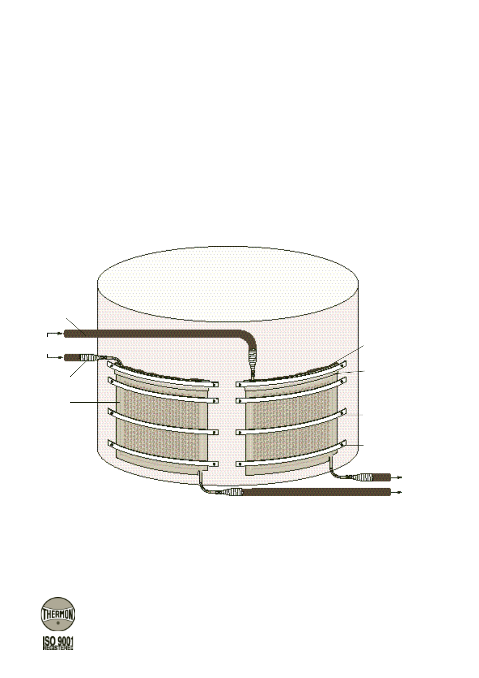
Illustration G: Typical HeetSheet Installation
8. Install ThermoTube
®
steam supply and return tubing to
collection manifolds and properly terminate all inlet and
outlet media connections using an FAK-7 end seal kit. The
steam supply should start at the highest point of the
HeetSheet so that flow is generally downward to avoid
trapping water during shutdown periods (see Illustration
G). Each panel should utilize a steam trap to prevent pref-
erential steam flow.
9. In situations where excessive moisture is expected or ther-
mal insulation will not be installed immediately following
HeetSheet installation, flashing should be installed using
waterproof mastic to prevent water from accumulating
behind the panel.
Inspection of System . . .
1. Thoroughly inspect banding after installation is complete
to verify proper tension.
2. After all connections to the supply header and collection
manifolds have been completed, test the circuit for leaks
by subjecting it to steam pressure equal to or greater than
that which is to be used in the system or preferably with
suitable hydrostatic tests. Repair any leaks and retest the
system.
HeetSheet
®
Vessel Heating/Cooling System
To Trap and
Condensate
Return Manifold
FAK-7
HeetSheet
40 x 6mm
Steel Strap
ThermoTube
Flashing
(if required)
Waterproof Mastic
Welded Stud
Attachment Method
From Steam
Supply Manifold
THERMON . . . The Heat Tracing Specialists
®
www.thermon.com
Corporate Headquarters
100 Thermon Dr.
•
PO Box 609
San Marcos, TX 78667-0609
•
U.S.A.
Phone: +1 512-396-5801
•
Facsimile: +1 512-396-3627
European Headquarters
Boezemweg 25
•
2641 KG Pijnacker
PO Box 205
•
2640 AE Pijnacker
•
The Netherlands
Phone: +31 (0) 15-36 15 370
•
Facsimile: +31 (0) 15-36 15 379