Installation procedures, Installation on valves and pumps – Thermon SafeTrace Steam Tracers User Manual
Page 5
INSTALLATION PROCEDURES
Installation on Valves and Pumps . . .
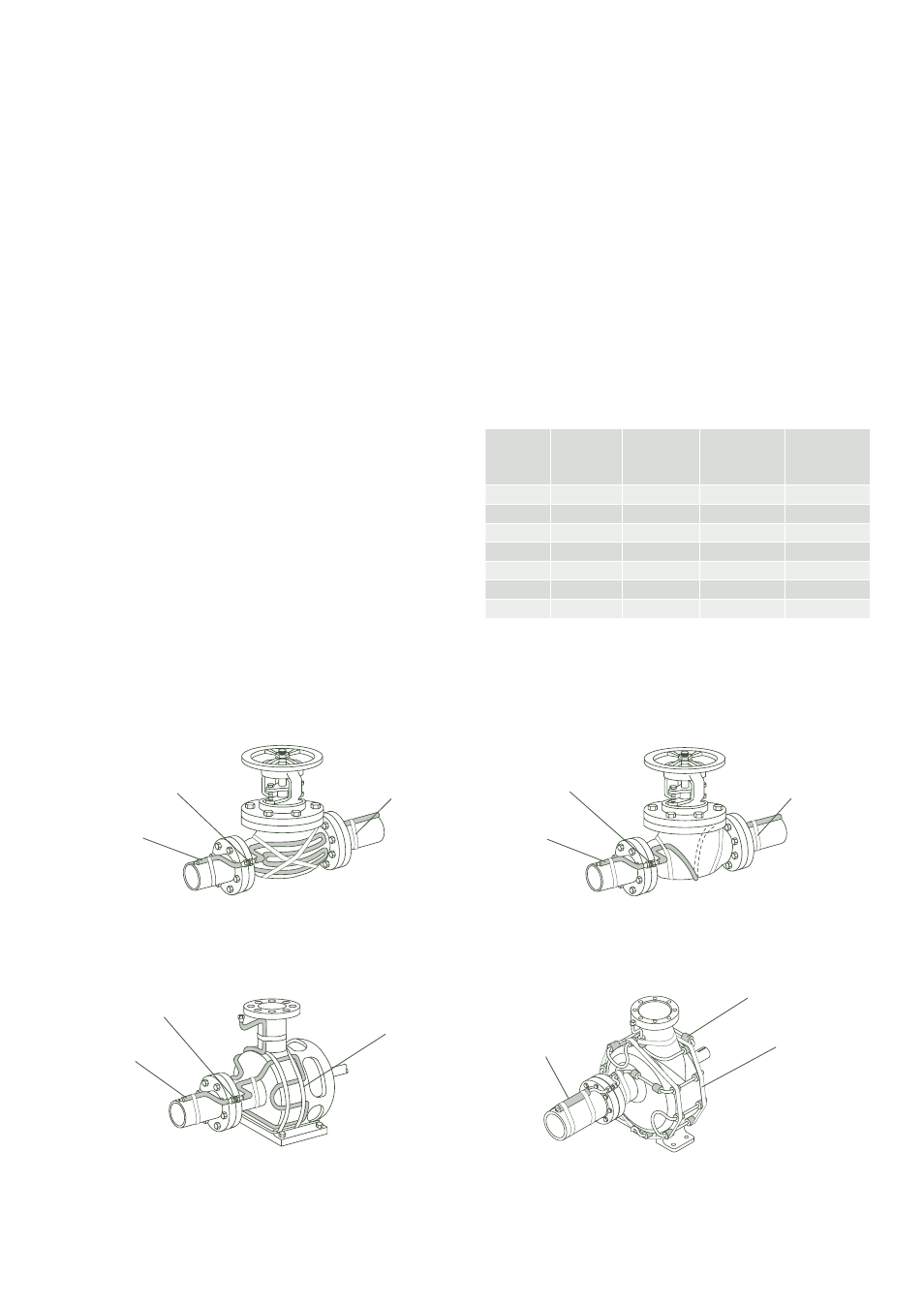
1. Install SafeTrace in accordance with Illustrations F and G
below. Secure tubing to valves and pumps using FT-1H at-
tachment tape as described on page 2.
2. Install SafeTrace tubing on valves and pumps in the form
of hairpin loops so that the tracer makes the least amount
of complete circles
1
. For valves sizes 50 mm and smaller
the tubing may be spiraled onto the valve. Where maxi-
mum coverage of a flanged valve is important for critical
tracing service such as sulfur, phthalic anhydride, benzoic
acid, etc., the tracer may be looped around the pipe at the
flanges before hair-pinning or looping the tracer onto the
valve. SafeTrace bends should be made in compliance with
the procedures described on page 3.
3. The outside diameters of SLS-IT and DLS-IT prevent the
tubing from being installed in a serpentine pattern on valves
and pumps. Depending on the level of heating required,
SafeTrace could simply pass by or be looped once around
the equipment. BTS may also be substituted in many ap-
plications around valves, pumps and equipment. As an
alternate, strip the jacket and insulation from the SLS-IT or
DLS-IT to allow for a smaller bending radius and use 25 mm
pieces as isolation sections as shown in Illustration G.
Refer to Table 4 for estimated SafeTrace requirements for
installation on valves.
Note . . .
1. For winterising, a single loop may be sufficient. For higher temperatures serpentined
is preferred.
2. Refer to the minimum bend radius for each SafeTrace type on page 3. For SLS and
DLS installations, BTS may be substituted around valves, pumps and equipment.
Illustration F: Typical Valve Detail
Illustration G: Typical Pump Detail
4. The number of loops depends on valve size and the abil-
ity to safely bend the tubing while keeping it free of kinks,
wrinkles or flattening. Valve body sizes and shapes vary
depending upon type of valve and manufacturer, there-
fore, it is difficult to make a specific statement on how the
valve should be wrapped with the tracer. Generally, for
valve sizes 50 mm and smaller, the tubing may be spiralled
around the valve when using SLS-IT or DLS-IT. Where
more heat is needed at a flanged valve, the tracer may be
looped around the pipe at the flange before hair-pinning
or looping the tracer onto the valve body and bonnet.
Table 4: Valve Allowance
2
4
SafeTrace
BTS Serpentined on Valve
Isolated Tracer Serpentined on Pump
BTS Single Loop Around Valve
BTS Serpentined on Pump
FT-1H Attachment Tape
FT-1H Attachment Tape
SafeTrace
SafeTrace
Tracer Isolation Sections
SafeTrace
FT-1H Attachment Tape
FT-1H Attachment Tape
Tubing Connection (Op-
tional)
Tubing Connection (Op-
tional)
Tubing Connection (Op-
tional)
Nominal
Valve Size
in (mm)
Pass by
Valve
m
Loop Once
Around Valve
m
BTS 3/8"
(10 mm)
m
BTS 1/2"
(12 mm)
m
2 (50)
0.23
0.5
0.9-1.5
0.9-1.2
3 (80)
0.29
0.6
1.2-3.1
1.2-1.5
4 (100)
0.30
0.7
1.8-3.0
1.5-2.1
6 (150)
0.41
1.0
2.7-4.6
2.1-3.4
8 (200)
0.42
1.2
3.7-6.1
2.7-4.6
10 (250)
0.46
1.4
4.6-7.6
3.0-6.1
12 (300)
0.50
1.6
5.5-9.1
4.6-7.6