Safetrace, Steam tracers – Thermon SafeTrace Steam Tracers User Manual
Page 2
SafeTrace
TM
Steam Tracers
1
The following installation procedures are suggested guide-
lines for the installation of SafeTrace BTS, SLS-IT and DLS-IT
tracers. They are not intended to preclude the use of other
methods and good engineering or field construction prac-
tices.
Receiving, Storing and Handling . . .
1. Inspect materials for damage incurred during shipping.
Report damages to the carrier for settlement.
2. Identify the SafeTrace tubing to ensure the proper type
and quantity has been received. Boxes and reels are
marked on the outside with the SafeTrace part number,
length, product description, weight and customer pur-
chase order number. Compare information on box or reel
with packing slip and purchase order to verify receipt of
correct shipment.
• Lengths shorter than 50 m are shipped in heavyweight
cardboard boxes.
• Lengths greater than 50 m are shipped on non-return
able
wooden reels.
3. The ends of SafeTrace tubing are factory-sealed to prevent
dirt, moisture and insect intrusion. As a preventive mea-
sure, keep ends sealed until final connections are made.
Cut ends may be temporarily sealed with plastic wrap and
tape.
4. Cardboard boxes and wooden reels of product should
be stored indoors away from standing water. However,
wooden reels may be stored outdoors using a protective
covering.
5. SafeTrace is shipped with the end of the tubing strapped
to the side of the wooden reel. Use caution when releasing
the end of the tracer from the reel as it is under tension
and may recoil when released.
Surface Preparation . . .
1. Verify that the process piping has been pressure-tested to
a pressure equal to or greater than that which will be used
under normal operation prior to installing SafeTrace tub-
ing. Repair any leaks before beginning installation of tracer
tubing.
2. Surface areas where SafeTrace is to be installed must be
reasonably clean. Remove dirt, rust and scale with a wire
brush and oil and grease films with a suitable solvent.
Tracer Layout . . .
1. Determine circuit lengths and number of fittings prior to
uncoiling the SafeTrace tubing since uncoiling and recoiling
will “work harden” the tubing.
2. For long straight piping runs, a 300 mm diameter expan-
sion loop must be provided at 18 to 30 m intervals.
3. If multiple passes are required, convection tracers may
be doubled back where allowable pressure drops are not
exceeded.
3. To uncoil and straighten the tubing, anchor the loose end
of the tubing on a flat surface and roll the hand coil or ship-
ping reel. If additional straightening is needed, apply tension
to the tube.
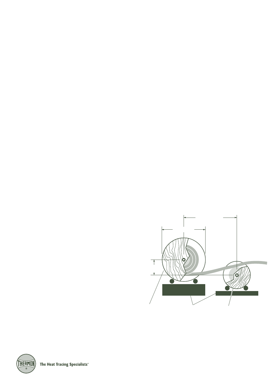
4. Wooden spools of SafeTrace containing long lengths of
tubing can be placed on a pay-off tray as shown in Illustra-
tion A below. To “pay-off” the SafeTrace tubing, place the reel
containing the tubing on one tray allowing the tracer tubing
to freely spool from the bottom of the reel.
5. Straighten the tubing by utilizing a counterspool located in
front of the reel containing the tracer tubing (see Illustration
A). The counterspool should be located at a distance of 2½
times the diameter of the SafeTrace reel. Include a vertical
offset of 200 to 250 mm between the reel centers.
2.5 x Diameter A
200-250 mm
Diameter A
SafeTrace Reel
Counterspool
Illustration A: Tracer Payout
Pay-off Trays