Ecm-os, Installation procedures – Thermon ECM-OS User Manual
Page 2
2
Item Quantity
Description
1
1
RTV Tube
2
1
Power Connection Boot
3
2
Ground Sleeve
4
1
End Cap
5
1
Tape Strip (PETK-3-ECM only)
6
1
End Termination Caution Label
Certifications/Approvals . . .
Kit Contents . . .
1
2
1
2
6
4
3
5
Item Quantity
Description
1
1
Stainless Steel Junction Box
2
1
Electronic Control Module w/ Terminal Blocks
(Refer to terminal specifications for maximum allowable wire size)
ECM Type*
C - Controler
L - Limiter
CL - Controller/Limiter
* The maximum pipe exposure temperature is limited to 232°C
Warnings . . .
• Due to the risk of electrical shock, arcing and fire caused
by product damage or improper usage, installation
or maintenance, a ground-fault protection device is
required.
• Installation must comply with Thermon requirements
(including form PN 50273U for Ex systems) and be
installed in accordance with the regulations as per the
norm EN IEC 60079-14 for hazardous areas (where
applicable), or any other applicable national and local
codes.
• Component approvals and performance ratings are
based on the use of Thermon specified parts only.
• Only appropriate Ex certified glands, blanks and
adaptors with a degree of protection of IP66 or better
may be used.
• De-energize all power sources before opening enclosure.
• Avoid electrostatic charge. Clean only with a damp cloth.
• Keep ends of heating cable and kit components dry
before and during installation.
• Minimum bending radius of heating cable is 32 mm
(except HPT is 57 mm and FP is 19 mm).
• Individuals installing these products are responsible
for complying with all applicable safety and health
guidelines. Proper Personal Protective Equipment (PPE)
should be utilized during installation. Contact Thermon
if you have any additional questions.
PETK Power and End Termination Kits (per cable)
PETK-1
for RSX, VSX, BSX
PETK-2
for KSX, HTSX
PETK-3-ECM
for HPT, FP
The following installation procedures are suggested guidelines
for the installation of the ECM-OS Kit. For translations other
than English and local language translation provided here,
please contact Thermon. The English language installation
procedure shall govern.
Receiving, Storing and Handling . . .
1. Inspect materials for damage incurred during shipping.
2. Report damages to the carrier for settlement.
3. Identify parts against the packing list to ensure the
proper type and quantity has been received.
4. Store in a dry location.
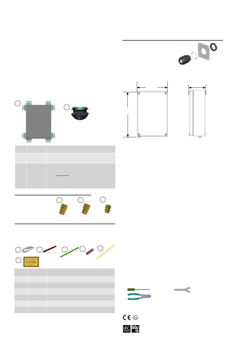
Dimensions . . .
II 2 (2) G Ex eb mb [ib] IIC T4, Ex tb IIIC T135°C SIRA 12ATEX5239X
II 2 (2) D Ex tb IIIC T135°C IP66 Db
International Electrotechnical Commission
IEC Certification Scheme for Explosive Atmospheres
SIR 12.0103X
Tools Required . . .
3 mm
8 mm
28 mm
33 mm
Order Separately . . .
IEK Insulation Entry Kit (per cable)
IEK-SXL: for RSX, VSX,
IEK-SXM for BSX
IEK-SXS for KSX, HTSX
IEK-HPT for HPT
IEK-RTD for RTD Lead Wire
Wire Cutters
ECM-OS
INSTALLATION PROCEDURES
90mm
177mm
237mm
Order Separately . . .
1 Power Gland
2 Heating Cable
3 RTD
3
2
1