Tecfluid MC-01 User Manual
Page 2
Cod:E-MI-2151061 I Rev:1
2
1 INSTALLATION
1.1 Mounting
The MC-01 control instrument is housed in a DIN 96 x 96 type plastic case intended to be mounted in a
front panel of an electrical control panel via a 90 x 90 mm +0.5mm/-0mm square hole. The electrical control
panel should have a minimum depth of 190 mm behind the front panel to take the MC-01.
IMPORTANT : In order to comply with the electrical safety requirements as per IEC 1010-1, the installation
of the equipment must take into account the following:
-
The equipment must be installed in the front panel of an electrical mounting cabinet, leaving
only the front of the equipment accessible to the operator.
-
A mains switch must be provided to disconnect the equipment. This switch must be marked
as the disconnecting device for the equipment and be within easy reach of the operator.
-
The mains supply must have an earth line.
1.2
Mains Connection
The connection of the equipment is via plug-in connectors, polarized to avoid mistakes when plugged
in. The connectors have screw terminals, as per VDE norms, to accept 1,5 mm
2
cable.
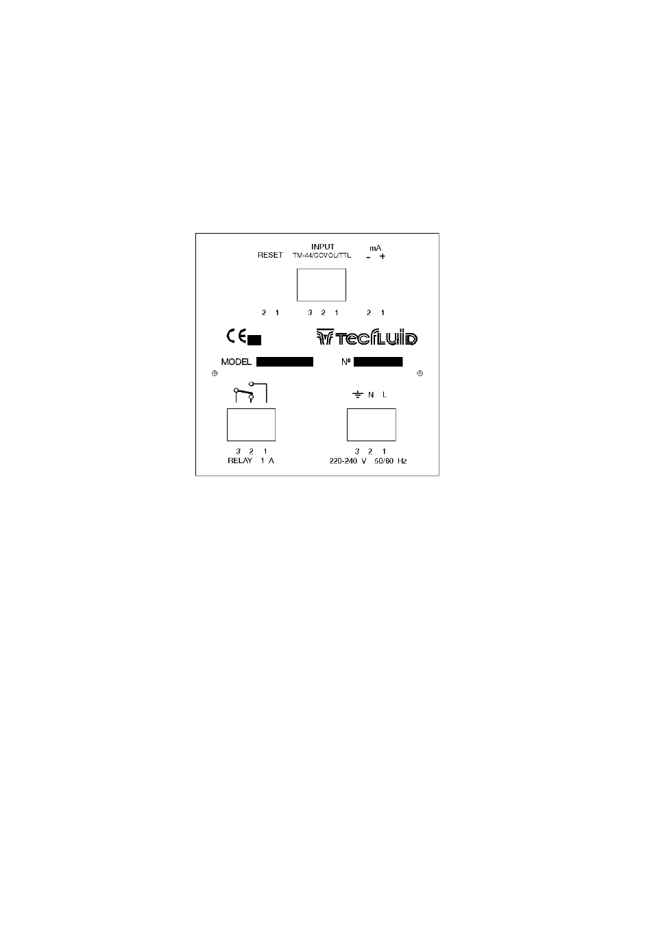
When we refer to the positions of the connectors, it is looking at the back of the MC-01.
The connector for the mains power supply is situated on the bottom right-hand side, in which the
power supply (voltage indicated below the connector) must be connected to terminals Nº1 and Nº2.
Terminal Nº3 should be connected to a good earth. The MC-01 has a Φ 5 x 20 mm mains fuse inside. The
nominal rating of this fuse depends on the mains voltage.