Tecfluid TH5 For DP Series User Manual
Page 4
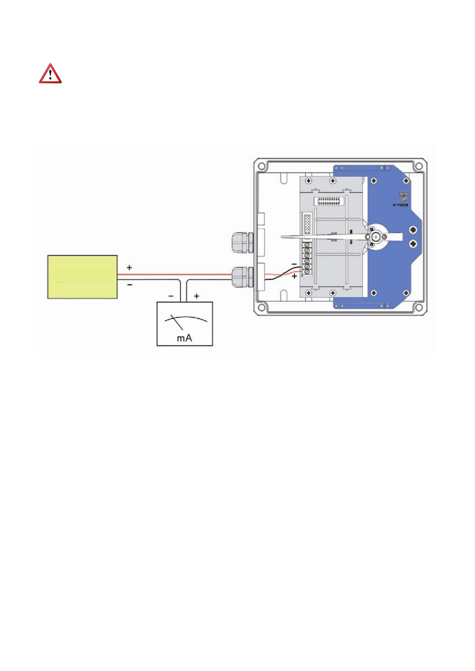
The connection is made in the terminal block. The positive terminal of the power supply is
connected to the position + and the positive terminal of the load in the position -. The
negative terminals of the power supply and the load are connected together. The
instrument works in a 2-wire system, that is, the supply and signal line is the same. It is
recommended to use a twisted pair wiring or shielded cable to avoid interferences in the
current loop.
3.2
Pulse output and reset
The pulse output is connected in the positions D and S of the terminal block. The output is
an N channel MOSFET isolated from the rest of the circuit and potential free. The S
terminal is the source and the D terminal is the drain.
The lower terminals marked as RESET are a reset input for the totalizer. It can be
connected a normally open potential free contact. It is important that the contact works
well with low level signals, to avoid noise effects.
The cable glands must be always closed. Entry of dust or some types of vapors can
damage the internal system of bearings and therefore the equipment.
Before connecting the power supply, you must be sure that the supply voltage is the
correct for the installation. The power supply voltage is indicated on the label of the
transmitter.
To help in the wiring of the equipment, the description of the terminals is marked on the
printed circuit next to the terminal strip.
3.1
Power supply and analog output
4
12 to 36 VDC