Tecfluid TH5 For DP Series User Manual
Page 3
3
1 INTRODUCTION
The Halltec V transmitter is an electronic position transducer with a microprocessor. The
instrument uses the Hall effect to capture the field of a magnet. This signal, after the micro-
controller processing, is converted to a current signal of 4-20 mA in a 2 wire loop. This
signal is proportional to the flow rate.
2 MODELS
2.1 TH5
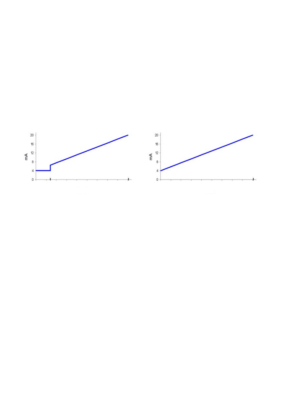
It is a 4 to 20 mA transmitter proportional to flow rate that incorporates a synchronized
pulse output. 4 mA corresponds to beginning of the scale. 20 mA corresponds to full scale.
Between the beginning of the scale and the first point of the scale the analog output is
constant at 4 mA, to avoid false readings of flow rate.
In the case of level measurement (LP series), the current range corresponds to the scale
at all the points.
1.
Example: Response of the TH5 transmitter
2.2 TH5H
It is a TH5 transmitter that incorporates HART
TM
protocol compatibility. With this protocol
the user can change the measuring range of the 4-20 mA loop, and data like flow rate and
accumulated volume, with its associated measuring units.
2.3
TH5T and TH5TH
They are the equivalent models to those of the sections 2.1 and 2.2, but in addition they
include a 8-digit totalizer (7 entire numbers and 1 decimal).
3 ELECTRICAL
CONNECTION
For the electrical connection, the Halltec V has a screw terminal strip.
For the electrical installation it is recommended to use multiple conductor cables with
individual cable sections in the order of 0.25 to 0.5 mm
2
in order to make it easier to
connect.
A twisted pair wiring should be used to avoid electrical interferences in the 4-20 mA loop.
In some instances, shielded cable may be necessary.
Before starting the installation, check that the cable glands are the right size for the cables
to be used, this will guarantee the instrument will stay watertight. The cable glands used
are for cables with outside diameters between 6 mm and 10 mm.
Peel the outside insulation to free the inner cables. It is recommended to tin the ends of
the wires to avoid loose ends. Pass the cables through the cable glands and screw down
in the corresponding positions of the terminal strip. Once the wiring is finished make sure
that the cables are well gripped by the cable glands to maintain the degree of protection.
First point of
the scale
Last point of
the scale
Flow rate
Last point of
the scale
Level