SVS 7 110V User Manual
Page 7
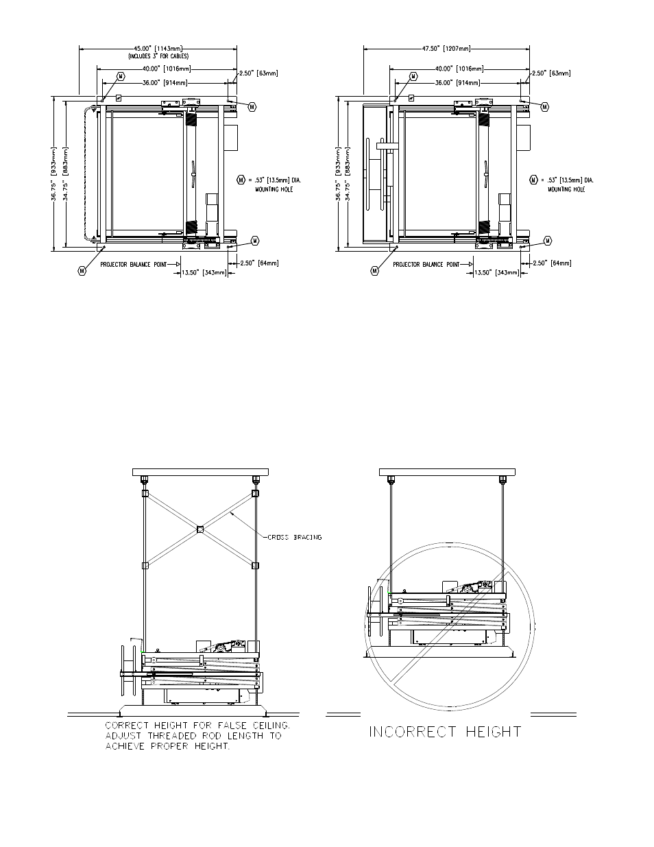
6. LIFT SUPPORTING STRUCTURE
The SVS 7 Lift should be mounted from four 1/2” rods. The mounting hole locations are marked with a
Figure 4. The thread rods must be supported by a rigid structure. If the threaded rods exceed more than 2-feet
(0.6 M) from the support structure to the lift's top mounting holes cross bracing should be installed between the
support rods. Figure 5 shows the cross bracing and the correct height for mounting the lift above the false
ceiling.
SVS 7 Lift Installation Instructions
Page 7 of 18
Figure 5. Cross Bracing & Correct Height
Figure 4. SVS 7 Series Top View
SVS 7-9, SVS 7-11, SVS 7-13 LIFTS WITH CABLE RETAINERS
SVS 7-15, SVS 7-18, SVS 7-20, SVS 7-22 LIFTS WITH CABLE RETRACTORS
This manual is related to the following products: