SVS 7 110V User Manual
Page 10
Remove the blocks by removing the screws and tie-raps holding them in place.
TO AVOID CABLE SPILLS
•
Do not push the lift bottom frame upwards once the Lift has been installed.
•
Make sure that there are no obstructions in the Lifts path. If the bottom frame is lowered onto an
obstruction the cable will slack and spill over the cable drum. If the cable spills over the cable
drum and the Lift is not stopped the cable will back-wind onto the cable drum causing severe
damage to the Lift and accessories.
8. ELECTRICAL CONNECTIONS
Electrical connections should be made at this time. The SVS 7 Lift requires 110V/60Hz at 2.3 Amps and is
supplied with a six foot power cord. The SVS 7 Lift is controlled with a 24VAC Low Voltage Controller called
the Wall Plate Controller. This controller can easily be connected to external controllers like Crestron, AMX,
Extron, etc. The Wall Plate Controller is supplied with 75-feet of cable (22 AWG, 9 conductor).
Wall Plate Controller Information
Wire Color
Connector Pin Function
Brown
3
Down to Show Position when 24VAC connected from Pin 1
Green
4
Down to Service Position when 24VAC connected from Pin 1
Red
2
Up when 24VAC connected from Pin 1
White
1
24 VAC Out (Common) (can be measured between Pin 1 and Pin 7)
Black
7
Power LED Return (Ground)
Orange
8
Power LED+
1. Make sure that the area below the Lift is clear and that all cable are clear of the Lift.
2. Apply power to the Lift by plugging it into an AC Outlet.
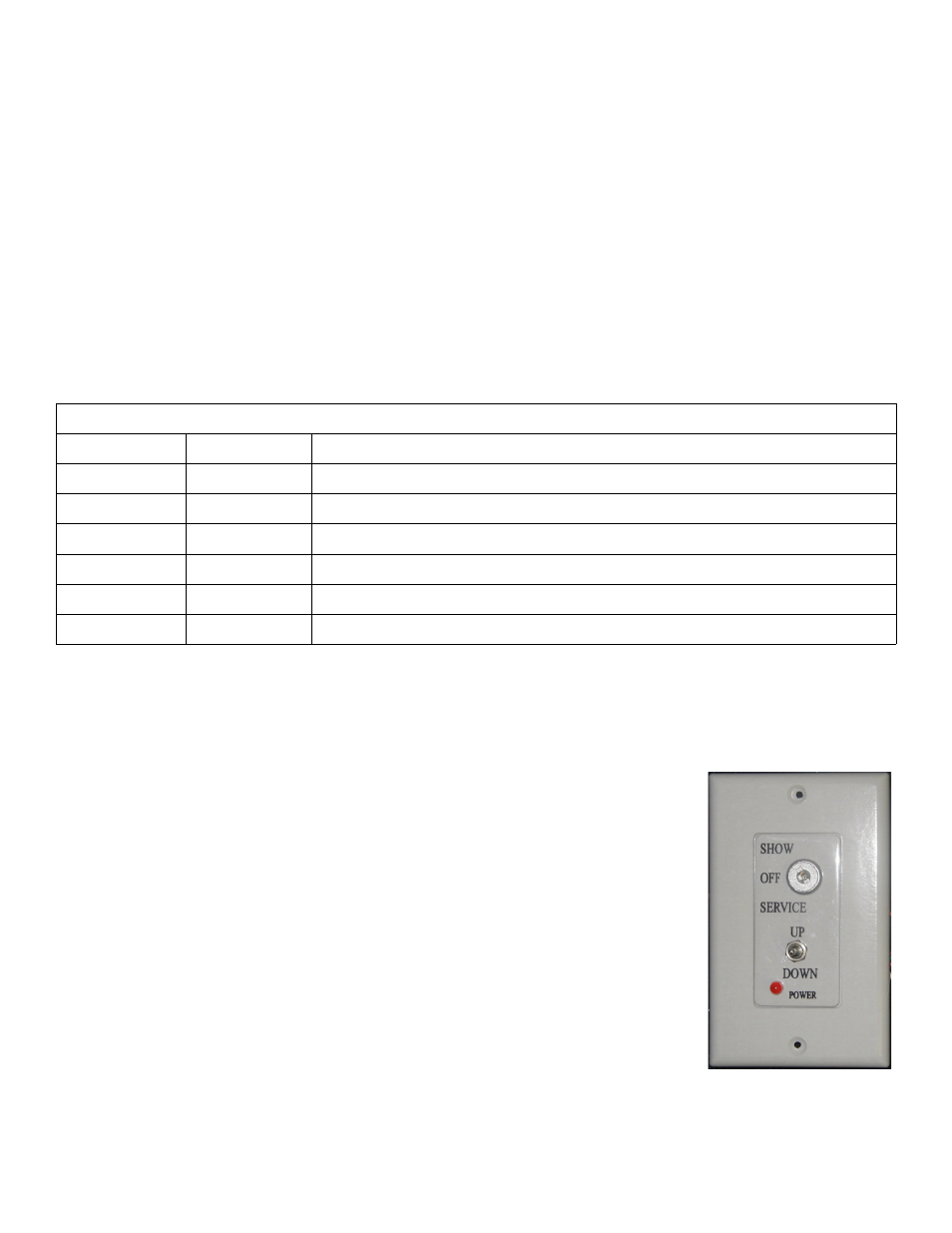
a. How to use the Wall Plate Controller
1. To lower the Lift to the Show position, turn the key switch to the Show
position and press the toggle switch down. The lift will lower as long as you
hold the toggle switch down, the lift will stop when the rear scissor roller
compresses the Show Position microswitch.
2. To lower the Lift to the Service position, turn the key switch to the Service
position and press the toggle switch down. The Lift will lower as long as
you hold the toggle switch down, the Lift will stop when the rear scissor
roller compresses the Down Limit microswitch. The Service position
bypasses the Show Position microswitch.
3. To raise the lift press the toggle switch up. The Lift will rise until the Up
Limit microswitches are compressed. The Lift will rise as long as you hold
the toggle switch up. The Lift can be raised with the key switch in either the
Show or Service positions.
4. The Off position on the key switch disables the Lift.
5. The Power light only comes on when the Lift is raising or lowering (Lift
motor turning), not when power is applied to the Lift.
Important: The toggles switch on the Wall Plate Controller must be pressed to raise or lower the Lift, releasing
SVS 7 Lift Installation Instructions
Page 10 of 18
Figure 8. Wall Plate
Controller