Super Systems 1500 VRSD User Manual
Page 7
Model 1500 VRSD Operations Manual
Super Systems Inc.
Page 7 of 28
2.2
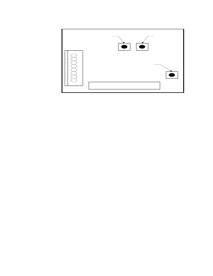
The sensor-sampling chamber is located in the bottom left of the unit. It is
the gray rectangular box with brass barb fittings on either side and a black
plastic gland protruding from the center.
2.3
The sensor probe is positioned in the sensor sampling chamber. It is held
in place by the nut on the black plastic gland.
3.0
Remove the sensor probe from the sensor-sampling chamber.
3.1
Loosen the black plastic gland nut and slowly slide the sensor probe out
through the airtight seal. Care must be taken when removing this sensor
probe, since the tip is very delicate and can be easily damaged if it is
mishandled. Note that the probe has white mark at the wire entry point,
which must be aligned with corresponding white mark in plastic gland when it
is re-inserted in the sampling chamber.
4.0
Install the sensor probe into the 75.3% salt solution.
4.1
Slip the black sensor gland (supplied in the calibration kit) over the sensor
probe with the sensor tip protruding from the threaded end of the gland and
the sensor wires being flush with the top of the rubber o-ring in the gland.
Tighten the gland around the sensor. This does not need to be done with a
wrench or other tools, but it does need to be tight enough to prevent ambient
air from contaminating the humidity level of the sampling chamber.
4.2
Remove the cap of the 75.3% salt solution and install the sensor gland
(with the sensor) into the salt solution. To increase the life of the calibration
salts, an effort should be made to minimize the amount of time that the salt
solution is exposed to the ambient air.
SPAN
BUTTON
(75.3)
ZERO
BUTTON
(11.3)
CAL
BUTTON
Dew Point Microprocessor Board