Calibration procedure for mkp - pkp – Super Systems 20PQ Calibration Manual User Manual
Page 4
4
Calibration procedure for MKP - PKP
1.2) "Hr" - FINAL SCALE VALUE
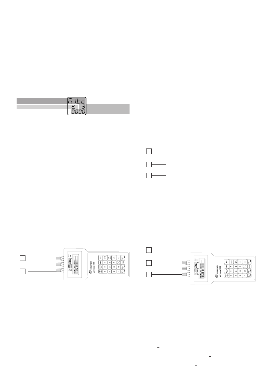
The upper display will show "ñ.I.tc", the lower display will show
"Hr" while "OFF" will appear on the middle display.
a) Set the calibrator to 60.000 mV (see Fig. 5).
b) Push
▲
pushbutton, the middle display will change to "On".
c) After few seconds, start calibration by pushing FUNC
pushbutton. At the end of this calibration routine, the instrument
will go to the next step.
1.3) "
∀.
∀.
∀.
∀.
∀.
" - TC INPUT CHECK
The lower and the middle display show "
∀
∀
∀
∀
∀.
" followed by the measured
value in counts as shown in the following figure:
Fig. 6
The "ñ.I.tc" "Hr" calibration is correct if the indication is equal to "
∀
∀
∀
∀
∀.
3
0000" + 10 counts.
a) Check the zero calibration, by setting the calibrator to 0.000 mV,
the read-out must be equal to "
∀
∀
∀
∀
∀.
0 0000" + 10 counts.
b) Check the half scale linearity by setting the calibrator to 30.000 mV.
The read-out must be "
∀
∀
∀
∀
∀.
1 5000" + 10 counts.
NOTE: when it is desired to use a different check point, the
following formula describes the ratio between the signal input and
the instrument read-out (in counts).
Instrument readout (in counts) =
input value
60 (mV)
•
30000
c) Push FUNC pushbutton, the instrument will go to the next
calibration group.
2) "ñ.I.CJ" - MAIN INPUT CALIBRATION - COLD JUNCTION
The upper display will show "ñ.I.CJ"
NOTE: make sure that "ñ.I.tc" "Lr" and "ñ.I.tc" "Hr" parameters are
correctly calibrated before to calibrate "ñ.I.CJ" parameter.
2.1) Lr - ACTUAL VALUE
The lower display will show "Lr"
a) Made the specific hardware setting as described at paragraph 2.
b) Measure the temperature close to terminals 1 and 3 using a
calibrator, for instance, the MEMOCAL (see Fig. 7).
Fig. 7
c) Wait a few minutes to allow the temperature stabilisation of the
entire system (sensor, calibrator and instrument).
d) The middle displays will show "OFF".
At the first pressure of
▲
or
▼
push-button, the middle display
starts to show a read-out value.
e) Using
▲
or
▼
push-button, set a read-out value equal to the
temperature measured by the measuring device (in C° and
tenths of °C).
f) After a few seconds, start the calibration by pushing FUNC
pushbutton. At the end of this calibration routine, the instrument
will go to the next step.
2.2) "
∀.
∀.
∀.
∀.
∀.
" - COLD JUNCTION COMPENSATION CHECK
The middle display will show "
∀
∀
∀
∀
∀.
".
The lower display will show the measured cold junction temperature
(in C° and tenths of °C).
a) Make sure that the cold junction temperature measured by the
instrument is equal to the value measured by the measuring device
(MEMOCAL).
b) Push FUNC pushbutton, the instrument will go to the next
calibration group.
3) "ñ.I.rt" - MAIN INPUT CALIBRATION - RTD INPUT
The upper display will show "ñ.I.rt".
NOTE: make sure that "ñ.I.tc" "Lr", "ñ.I.tc" "Hr" and "ñ.I.CJ" param-
eters are correctly calibrated before to calibrate "ñ.I.rt"
parameter.
3.1) "Lr" - INITIAL SCALE VALUE
The lower display will show "Lr"
a) Made the specific hardware setting as described at paragraph 2.
b) Made a short circuit between terminals 1, 3 and 4 as shown in
Fig. 8.
Fig.8
c) The upper display will show "ñ.I.rt", the lower display will show
"Lr" while "OFF" will appear on the middle display.
d) Push
▲
pushbutton, the middle display will change to "On".
e) After a few seconds, start the calibration by pushing FUNC
pushbutton. At the end of this calibration routine, the instrument
will go to the next step.
3.2) "Hr" - FINAL SCALE VALUE
The upper display will show "ñ.I.rt", the lower display will show
"Hr" while "OFF" will appear on the middle display.
a) Connect the instrument under test to the calibrator as shown in
Fig. 9.
Fig.9
b) Set the calibrator to 375.00
Ω
.
c) Push
▲
pushbutton, the middle display will change to "On".
d) After a few seconds, start the calibration by pushing FUNC
pushbutton. At the end of this calibration routine, the instrument
will go to the next step.
3.3) "
∀.
∀.
∀.
∀.
∀.
" - RTD INPUT CHECK
The lower and the middle display show "
∀
∀
∀
∀
∀.
" followed by the measured
value in counts (see fig 6).
The "ñ.I.rt" "Hr" calibration is correct if the indication is equal to "
∀
∀
∀
∀
∀.
3
0000" + 10 counts.
a) Check the zero calibration, by setting the calibrator to 0.00
Ω
, the
read-out must be equal to "
∀
∀
∀
∀
∀.
0 0000" + 10 counts.
b) Check the linearity by setting the calibrator to 175.00
Ω
. The
read-out must be "
∀
∀
∀
∀
∀.
1 4213" + 10 counts.
3
+
_
1
RTD
1
3
4
1
3
4
Selected calibration group
Check simbol
Measured or generated
value (in counts)