1 general guidelines for calibration, 2 preliminary hardware settings – Super Systems 20PQ Calibration Manual User Manual
Page 2
2
Calibration procedure for MKP - PKP
INSTRUMENT CALIBRATION
PROCEDURES
1 GENERAL GUIDELINES FOR CALIBRATION
For an accurate calibration it is necessary to proceed as follows:
a) - The instrument under calibration should be mounted in its case in
order to keep the internal temperature stable.
b) - The ambient temperature should be stable.
Avoid any drift due to air-conditioning or others.
c) - The relative humidity should not exceed 70%.
d) - The instrument must be in ON condition from 20 minutes at least.
e) - Operate, possibly, in an environment with no electromagnetic
disturbances.
f) - During calibration, connect to the instrument one input at a time.
g) - Before to execute each calibration, be sure that the specific
hardware setting has been made (see "Preliminary hardware
setting" paragraph).
For this calibration procedure it is necessary to use calibrators with
the following accuracy and resolution:
ACCURACY
1) For current input: + 0.025% output + 0.0025% range + 0.01
µ
A
2) For voltage input : + 0.005% output + 0.001% range + 5
µ
V
3) For TC input: + 0.005% output + 0.001% range + 5
µ
V
4) For RTD input: + 0.02 % + 0.0025
Ω
/decade.
5) For cold junction compensation: better than 0.1 °C
RESOLUTION
1) For current input: 0.5
µ
A
2) For voltage input: 100
µ
V
3) For TC input: 1
µ
V
4) For RTD input: 10 m
Ω
5) For cold junction compensation: better than 0.1 °C
2 PRELIMINARY HARDWARE SETTINGS
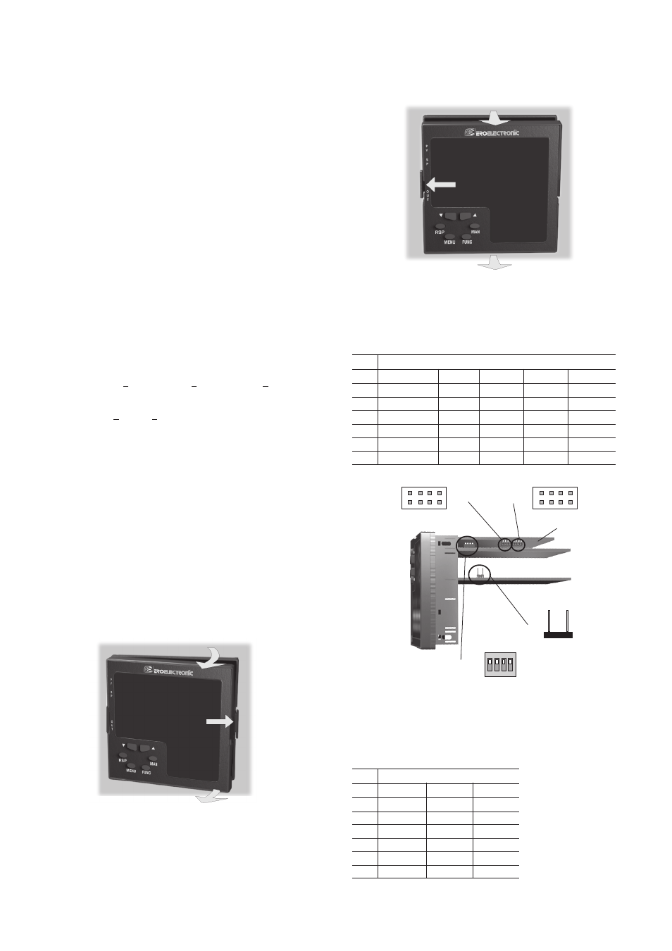
2.1 HOW TO REMOVE THE INSTRUMENT
FROM ITS CASE
1) Switch off the instrument.
2) Push gently the lock A on the right.
3) While the lock A is maintained out, slide out the right side of the
instrument (see fig. 1).
Fig. 1
4) Push gently the lock C on the left.
5) While the lock C is maintained out, slide out the instrument
(see fig. 2).
Fig. 2
2.2 MAIN INPUT SELECTION
Set J103 (see fig. 3) according to the desired input type as shown in
the following table.
J103
INPUT TYPE
T/C, RTD,CJ
60 mV
5 V
10 V
20 mA
1-2
open
open
close
open
open
3-4
open
open
close
close
open
5-6
open
open
open
open
close
7-8
open
open
open
open
close
5-7
close
close
open
close
open
6-8
close
close
open
open
open
Fig. 3
2.3 AUXILIARY INPUT SELECTION (option)
Set J102 (see fig. 3) according to the desired input type as shown in
the following table.
J102
INPUT TYPE
5 V
10 V
20 mA
1-2
close
open
open
3-4
close
close
open
5-6
open
open
close
7-8
open
open
close
5-7
open
close
open
6-8
open
open
open
A
B
B
D
C
D
1 3 5 7
2 4 6 8
1 3 5 7
2 4 6 8
J102
J103
CPU
card
1 2 3 4
ON DIP
V301
J205