Architecture, Smt8036e, Software defined radio development system – Sundance SMT8036E User Manual
Page 6
Version 1.0
Page 6 of 12
SMT8036E User Manual
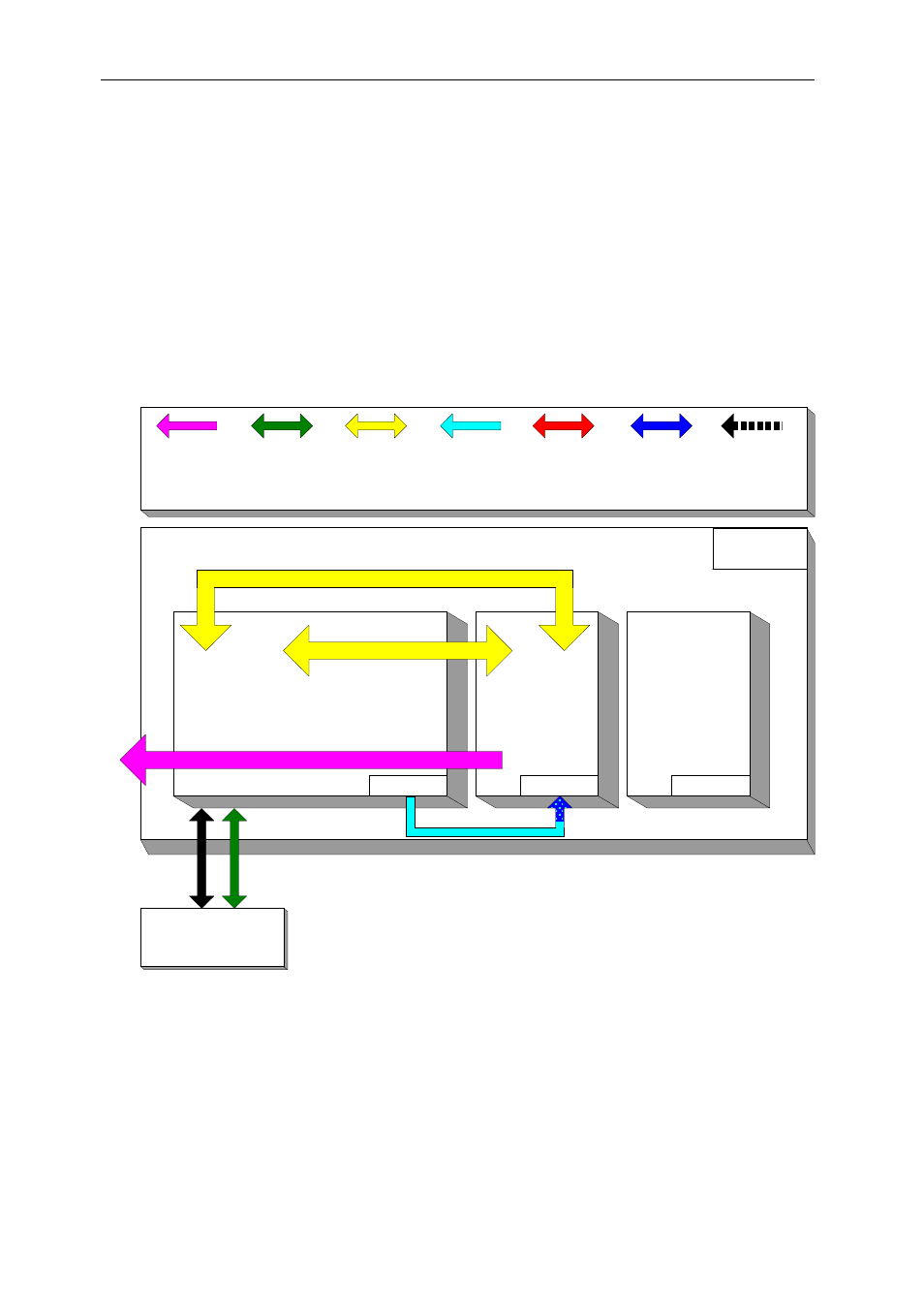
The SMT8036E application causes the DSP on the SMT365E to configure the DAC
of the SMT370 to generate a continuous sine wave via a first SHB connection. DAC
outputs are looped onto the ADCs inputs. The DSP grabs data from both channels
and stores them into a file, which can be read by a Matlab application for data
displaying and FFT processing. Sampling clocks (100MHz for the ADCs and 160MHz
for the DAC) are generated by on-board clock synthesizers.
Architecture.
The following diagram shows the architecture of the SMT8036E system:
Spare
SMT310Q
PCI-Host
System
Data
SDB
Connection
Control
Comm
Port
Data
Comm
Port
Analogue
Connection
Processing
TIM 4
Data
SHB
Connection
Data
Global Bus
Connection
SMT370
DAQ
Module #2
TIM 3
SMT365E
DSP
Module #1
TIM 1
SMT511-320 SHB Cable
SMT511-320 SHB Cable
SMT550-4-MMBX AnalogueCables
SMT8036E
Software Defined Radio Development System