Pci-to-smt130 interrupts, Interrupt registers, Figure 7 : pci to smt130 interrupts – Sundance SMT130 v.1.0 User Manual
Page 33: Pci bridge
User Manual (QCF42); Version 3.0, 8/11/00; © Sundance Multiprocessor Technology Ltd. 1999
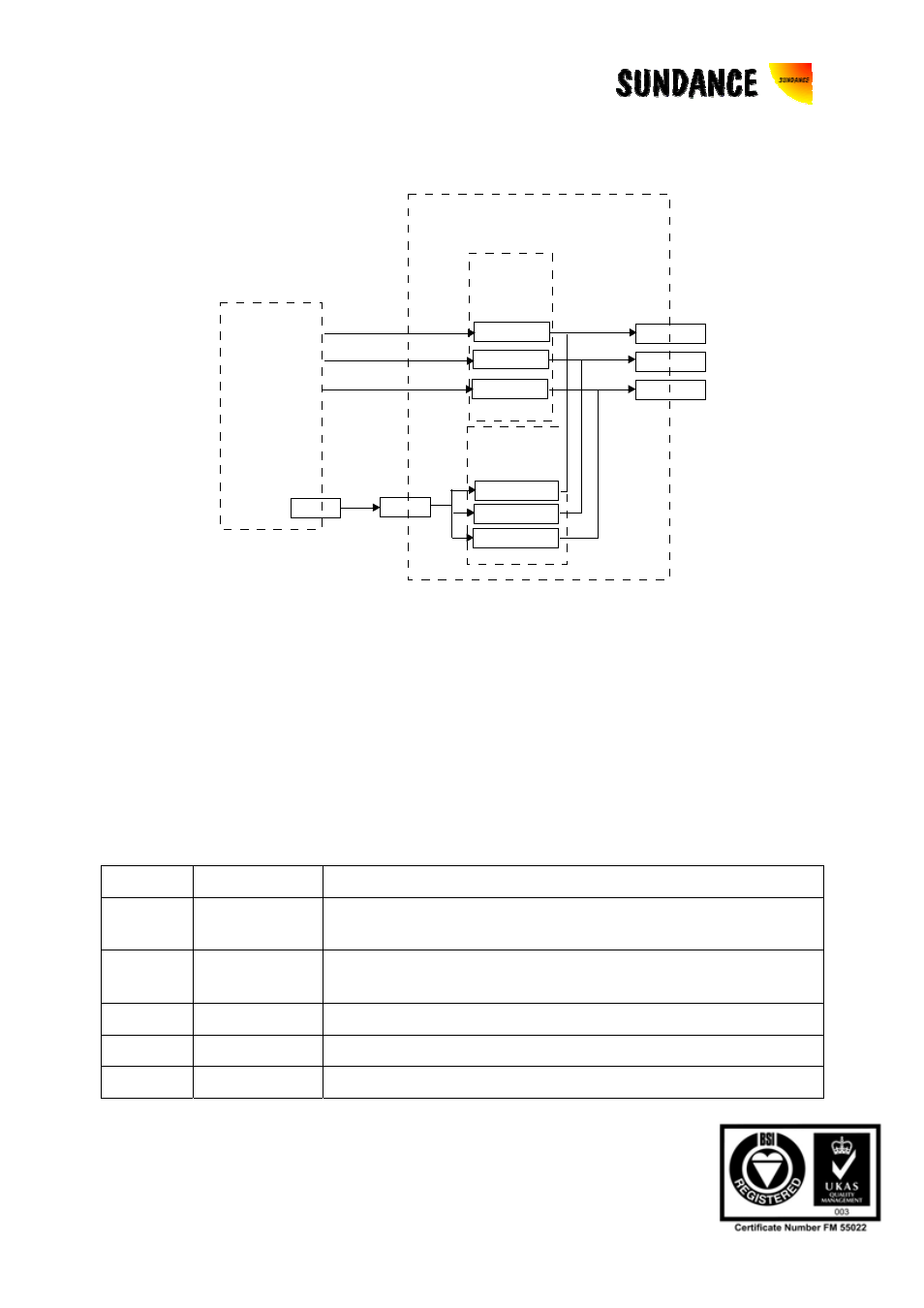
13.2 PCI-To-SMT130 Interrupts
TIMIIOF0
TIMIIOF1
TIMIIOF2
CONTROL
REGISTER
CONTROL CPLD
LINT
LINT
LINT can
be caused
by any PCI
interrupt
e.g. Mailbox
IIOF0
IIOF1
IIOF2
PCI
Bridge
INTREG
REGISTER
TIMIIOF0 IE
TIMIIOF1 IE
TIMIIOF2 IE
Figure 7 : PCI to SMT130 Interrupts
13.3 Interrupt Registers
The following register are used to control PCI-To-DSP and DSP-To-PCI interrupts:
Note that Control Register (Offset 0x14, BAR1) and Interrupt Control Register (Offset
0x18, BAR1) are also used to control interrupts.
13.3.1 PCI Interrupt Configuration Register(Offset 0x4C, BAR0)
Bits Name
Description
31
MAILBOX
Mailbox Interrupt Enable: Enables a PCI interrupt from the
mailbox unit
30
LOCAL
Local Bus Direct Interrupt Enable: Enables direct local bus
to PCI interrupts
29
MASTER_PI PCI Master Local Interrupt Enable: (see V3 datasheet)
28
SLAVE_PI
PCI Slave Local Interrupt Enable: (see V3 datasheet)
27
OUT-POST
I2O Outbound Post List Not Empty: (see V3 datasheet)