Jtag controller, Figure 1 : tbc data routing, 9 jtag controller – Sundance SMT130 v.1.0 User Manual
Page 20
User Manual (QCF42); Version 3.0, 8/11/00; © Sundance Multiprocessor Technology Ltd. 1999
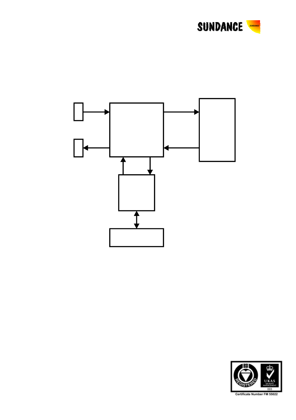
9 JTAG
Controller
The SMT130 has an on board Test Bus Controller (TBC). The TBC is controlled from
the PCI bus giving access to the on site TIM and/or any number of external TIMs.
The TBC is a SN74ACT8990 from Texas Instruments. Please refer to the Texas
Instruments data sheet for details of this controller. The TBC is accessed in I/O space
at the Base address + 0x80.
Test Bus
Switching
Matrix
Test Bus
Controller
PCI bridge
TIM
Site
JTAG Stacking
Connectors
J2
J1
Figure 1 : TBC Data Routing
The SMT130 can operate in two TBC modes; Master mode and Slave mode. In
Master mode, the Test Bus Controller on the SMT130 drives the JTAG scan chain
through the TIM site on the SMT130. If the site is not populated with a TIM then the
modules SENSE signal is used to enable a tri-state buffer connecting the TDI and
TDO (JTAG Data In and Data Out) on the site, maintaining the integrity of the JTAG
data path. This switching is automatic. The External JTAG Connector J2 is intended
to connect to a second SMT130 in the PCI-104 stack. When this is the case the
SMT130 automatically detects the device and routes the test data accordingly.
The SMT130 is configured in Slave mode if the TBC and JTAG chain from another
SMT130 is being used. In this case the JTAG master is connected to the SMT130 on
connector J1. When stacking SMT130 carriers in a PCI-104 system, the