Digin register, Digout register, Vstatus register – Sundance SMT128 User Manual
Page 7
Preliminary
Page 7 of 15
SMT128 User Manual
D0 -> logic 1 = Watchdog is reset using a write to the WDOG RST register.
At reset the value of this signal is ‘0’ i.e. internal oscillator is selected.
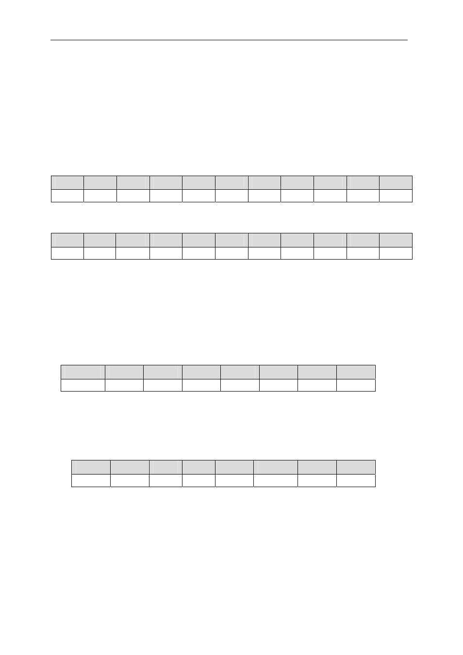
DIGIN Register
There are 22 digital input lines connected to the DIN connector PL1.
This is a Read-only register and when read returns the current value on DigIn signals
as illustrated below.
D21
D20
D19
D18
D17
D16
D15
D14
D13
D12
D11
DigIn22 DigIn21 DigIn20 DigIn19 DigIn18 DigIn17 DigIn16 DigIn15 DigIn14 DigIn13 DigIn12
D10
D9
D8
D7
D6
D5
D4
D3
D2
D1
D0
DigIn11 DigIn10 DigIn9 DigIn8 DigIn7 DigIn6 DigIn5 DigIn4 DigIn3 DigIn2 DigIn1
DIGOUT Register
There are 8 digital output lines, which are connected to the DIN connector PL1.
Each output can be set to the desired logic level by writing to this register using the
Global Bus data bits illustrated below.
D7
D6
D5
D4
D3
D2
D1
D0
DigOut8 DigOut7 DigOut6 DigOut5 DigOut4 DigOut3 DigOut2 DigOut1
VSTATUS Register
When Reading this register the following values are read.
D7
D6
D5
D4
D3
D2
D1
D0
X X X
S0INT1
S0INT0
TERMINAL
Addr1
Addr0
Addr0, Addr1 -> Board address, reflects the state of the Addr0 and Addr1 signals
on the PL1 connector.
TERMINAL ->
When a VT100 terminal, or compatible, is connected to the front
panel this bit is logic ‘1’.