Studio Technologies 60 User Manual
Page 11
Issue 2, March 1998
Model 60/61 User Guide
Page 14
Studio Technologies, Inc.
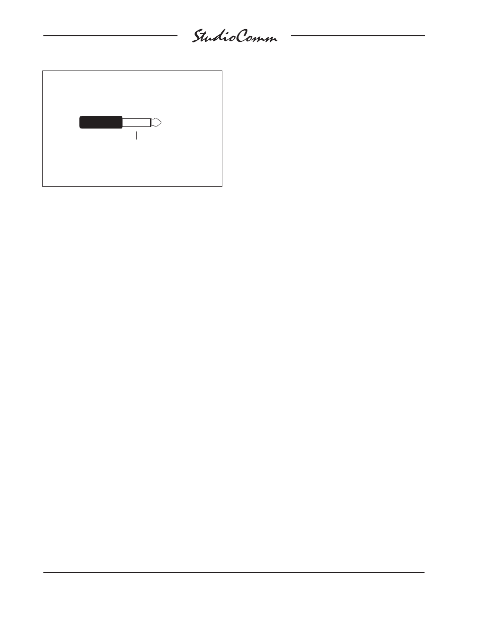
Access to the control room mute function
is via a ¼-inch jack located on the Model
60’s back panel. Mute is enabled when-
ever the tip lead is shorted (connected) to
the sleeve lead. Using a ¼-inch phone
plug, connect a normally open contact to
the tip and sleeve. The contact must be
capable of handling a current of 7 milliam-
peres at 15 volts DC.
Dub Output
The Model 60 contains a stereo line-level
output which is intended for connection to
a variety of analog audio devices. The dub
output is electronically balanced and is
capable of driving loads of 600 ohm or
greater. With the input impedance of most
audio devices being 10k ohms or greater,
the dub output can easily drive 10 or more
devices simultaneously.
Prepare the mating connectors (plugs) so
that tip is signal high (+ or hot), ring is low
(– or cold), and sleeve is shield. To con-
nect to an unbalanced load connect the tip
to high (+ or hot), and both the ring and
sleeve to shield.
Headphone Output
The Model 60 contains headphone output
jacks on both the front and back panels.
For flexibility separate amplifier circuits
support each jack; connecting to the front
panel jack doesn’t affect the jack on the
back and vice-versa. The simplest way of
using the headphone output is simply to
plug a pair of headphones into the front
panel jack. In other applications it may be
convenient to wire connector panels lo-
cated in a control room, studio, or voice-
over booth to the back-panel headphone
output.
Using a ¼-inch phone plug, the head-
phone output should be wired with tip as
left channel, ring as right channel, and
sleeve as output common/shield.
The sonic quality of the headphone out-
puts are such that they are suitable for use
as additional unbalanced line-level out-
puts. If it is anticipated that the installation
may benefit from this ability it may be
helpful if the back-panel headphone output
is wired into jacks on a patch bay. In this
way this headphone output can be rapidly
connected to other pieces of equipment.
Connecting the Model 60 to the
Model 61
A standard 5-conductor MIDI-style cable
is used to connect the Model 60 to the
Model 61; a cable is included with each
system. Just connect the cable between
the female 5-pin DIN-type connectors on
the back panels of both the Model 60 and
61, and viola, you’re done.
Note: If you require a longer cable, be
certain to buy a MIDI-type cable that has
all 5 pins wired. If they aren’t all con-
nected, the Model 61 will not operate. For
best performance, the cable that connects
the Model 60 with the Model 61 should be
limited to 50 feet (15.4m).
Control Room Mute Connection
Tip: Mute ( + )
(Short to sleeve
to enable mute)
(Switchcraft No. 280, Neutrik NP2C or equivalent)
Sleeve: Shield