Studio Technologies 60 User Manual
Page 10
Model 60/61 User Guide
Issue 2, March 1998
Studio Technologies, Inc.
Page 13
–10dBV signal levels. Switches on the
Model 60’s back panel allow the input
sensitivity to be changed at any time.
Prepare the mating connectors (plugs) so
that tip is signal high (+ or hot), ring is low
(– or cold), and sleeve is shield. With an
unbalanced source connect the tip to high
(+ or hot), and both the ring and sleeve to
shield. If connecting to an unbalanced
source in this manner results in hum or
noise, connect tip to high (+ or hot) and
ring to shield; leave the sleeve
unterminated.
As an installation aid, a connection made
only to an input’s L/Mono jack routes the
signal to both the left and right input cir-
cuitry. This allows a monaural signal to be
utilized in a 2-channel mono format. If you
wish to have a mono input connected only
to the left input, simply insert an untermin-
ated plug into the associated right input.
This will break the “normal” connection
that links the left and right input circuits.
Control Room Output
The Model 60 contains a stereo line-level
output for connection to an audio power
amplifier. This audio amplifier serves a
pair of loudspeakers that are located in the
control room. (Of course the control room
output can be connected to loudspeakers
that contain integral power amplifiers, such
as the products from Genelec.) The output
is electronically balanced and capable of
driving loads of 600 ohms or greater. In
most situations the best performance will
be obtained if the audio amplifier’s input
sensitivity is set to near maximum. Refer
to the Technical Notes section for details
on setting amplifier sensitivity.
Prepare the mating connectors (plugs) so
that tip is signal high (+ or hot), ring is low
(– or cold), and sleeve is shield. To con-
nect to an unbalanced load connect the tip
to high (+ or hot), and both the ring and
sleeve to shield.
Control Room Mute
In special applications, specifically on-air
broadcast, it may be desirable to allow
the control room output to be manually or
automatically muted. This can serve two
purposes: eliminating the need to remem-
ber to “turn down” the level control on the
Model 61 Control Console, and providing
a full mute of the control room output
signal. The Model 61’s rotary control
gives a 70dB attenuation range, perfect
for normal operation but not the full mute
that may be required when a “live” micro-
phone is located adjacent to the control
room speakers.
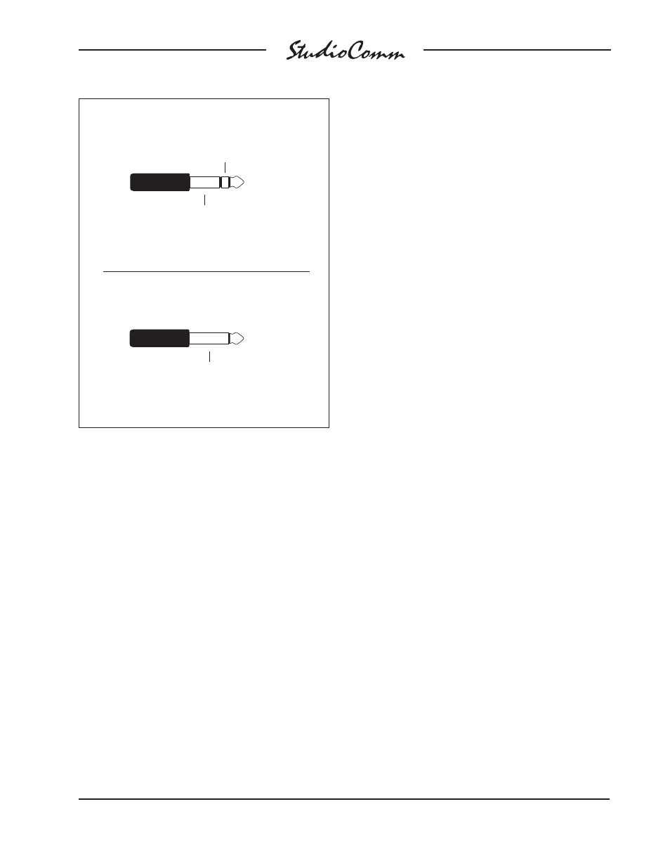
Balanced Line Input Connection
Tip: Input ( + )
(Switchcraft No. 297, Neutrik NP3C or equivalent)
Unbalanced Line Input Connection
Tip: Input ( + )
(Switchcraft No. 280, Neutrik NP2C or equivalent)
Sleeve: Shield
Ring: Input ( – )
Sleeve: Shield