Studio Technologies 5152 V.3 User Manual
Page 24
Issue 2, June 2013
Model 5152 User Guide
Page 24
Studio Technologies, Inc.
Model 5152
Video Generator/Audio Embedder Module
number of the installed firmware (embed-
ded software). Upon power being applied
to the module:
1. The LEDs will perform a “walk-through”
test, with each LED briefly lighting in a
sequence.
2. Next the Power LED will light and
remain lit.
3. Very shortly after the Power LED lights
the USB Activity LED will light to in-
dicate that the MCU firmware version
is being displayed by the eight Digital
Audio Inputs Signal Present LEDs. The
top row of four LEDs will display the
major version number with a range of
1-4. The bottom row of four LEDs will
display the minor version number with
a range of 0 (no LED lit) to 4. Refer to
Figure 11 for details.
4. After a few seconds the USB Activity
LED will go out and the FPGA firmware
version will be displayed by the eight
Digital Audio Inputs Signal Present
LEDs. The top row of four LEDs will
display the major version number with
a range of 1-4. The bottom row of four
LEDs will display the minor version
number with a range of 0 (no LED lit)
to 4. Refer to Figure 11 for details.
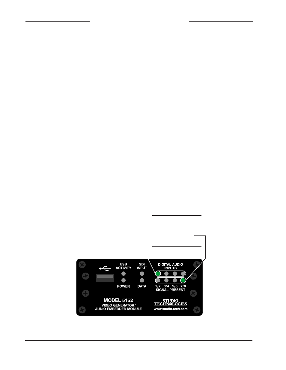
Figure 11. Detail of front panel showing the LEDs that
display the MCU and FPGA firmware versions. In this
example, the version shown is 1.4.
Major Version Number
1 2 3 4
O O O
O O O
.1 .2 .3 .4
Minor Version Number
(
No LED lit indicates .0)
5. After a few seconds the LEDs will be-
gin performing in their normal operating
manner. The Power LED should remain
lit. The USB Activity LED will only be ac-
tive when a USB flash drive is inserted
and file transfer activity is taking place.
The SDI Input LED will light whenever
a valid SDI signal is connected to either
the coaxial (BNC) input or the optical
input, depending on the module’s ca-
pability and configuration setting. The
Data LED will light whenever local data
is received via the RS-485 data bus
from a Studio Technologies’ Model 5190
Remote Access Module. If digital audio
input signals have been selected to
be embedded their associated Digital
Audio Inputs Signal Present LEDs
will light whenever signal levels are
–40 dBFS or greater.
Once a user gets accustomed to what’s
actually happening during power up it
should be fairly straightforward to “read”
the version numbers.