Configuration, Configuration, Audio embedding – Studio Technologies 5152 V.3 User Manual
Page 13: Sdi input select
Model 5152 User Guide
Issue 2, June 2013
Studio Technologies, Inc.
Page 13
Model 5152
Video Generator/Audio Embedder Module
Configuration
Ten DIP switches are used to configure
the Model 5152’s operating functions. The
functions relate to SDI input selection,
audio embedding configuration, SDI output
image rate/format mode, RS-485 address,
and moving image overlay. The ten switch-
es are located on the two circuit boards
that comprise the Model 5152. Five of the
switches are on the FPGA board which is
the lower board. The other five switches
are on the MCU board which is the upper
board. The switches are a “piano key” type
with their up position being defined as off
and their down position defined as on.
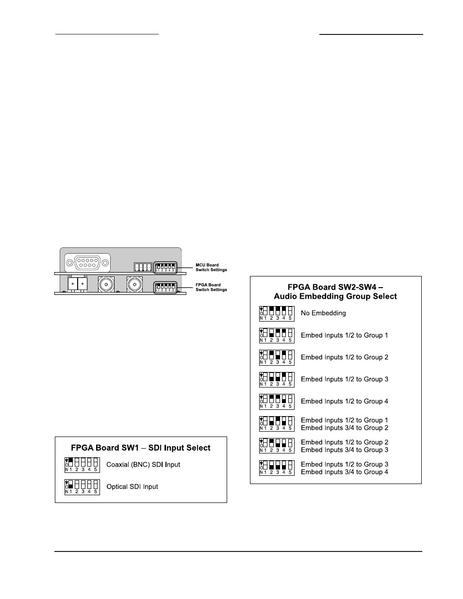
Switch 1 on the FPGA board is used to
select which SDI input will be active. When
the switch is in its off (up) position the
coaxial (BNC) input is selected. When the
switch is in its on (down) position the opti-
cal input is selected. Of course the optical
input will only function if a factory-supplied
SFP module is physically present.
Audio Embedding
One of the strengths of the Model 5152 is
its ability to select which of the four digi-
tal audio inputs will be active and where
their signals will be embedded into the
SDI output “stream.” Switches 2, 3, and 4
on the FPGA board are used to configure
the embedding function, allowing selection
from among eight choices.
Figure 6. SDI Input Select Settings
Figure 5. Rear view of Model 5152 showing
FPGA and MCU board configuration switches
SDI Input Select
The Model 5152 is capable of having its
SDI input in the form of a coaxial signal
(BNC connector) or an optical signal (SFP
module). Each version of the Model 5152
supports the coaxial (BNC) input. The opti-
cal input is an option and may or may not
be present on the specific module you are
configuring.
Figure 7. Audio Embedding Group Select
Settings