Identifying the installed firmware versions – Studio Technologies 5150 V.3 User Manual
Page 20
Issue 1, June 2013
Model 5150 User Guide
Page 20
Studio Technologies, Inc.
Model 5150
Video Generator Module
Note: It’s possible that during the update
process any LEDs located on the USB
flash drive may light steadily or flash with
varying patterns. These actions are not
significant to the Model 5150’s firmware
update process. (The status LEDs on vari-
ous USB flash drives seem to behave in
different ways so there are no universal
patterns that can be identified.)
Identifying the Installed
Firmware Versions
The four status LEDs on the front panel
of the Model 5150 are used during the
power-up sequence to identify the version
number of the installed MCU and FPGA
firmware (embedded software). While the
display method is a bit unique, once a
user gets accustomed to what’s actually
happening during power up it should be
fairly straightforward to “read” the version
numbers.
To identify the installed firmware versions:
1. Power up the Model 5150. The four
LEDs will perform a “walk-through”
test, with each LED briefly lighting
in a sequence.
2. After a slight pause one of the four
LEDs will light briefly. This will indicate
the major number of the MCU’s firm-
ware version. The LED will stop light-
ing then another one of the four LED
will light briefly to indicate the minor
number of the MCU’s firmware version.
The range of each is 1-4. A period (.) is
inserted between the major and minor
numbers.
As an example, if the USB Activity LED
lights first followed by the SDI Input
LED lighting this would indicate version
1.2 of the MCU firmware.
3. After another slight pause one of the
LEDs will light briefly. This will indicate
the major number of the FPGA’s firm-
ware version. The LED will stop lighting
then another one of the four LED will light
briefly to indicate the minor number of
the FPGA’s firmware version. The range
of each is 1-4. A period (.) is inserted
between the major and minor numbers.
As an example, if the SDI Input LED
lights twice this would indicate version
2.2 of the FPGA firmware.
4. After a final short pause the four LEDs
will begin performing in their normal op-
erating manner. The Power LED will light
and remain lit. The USB Activity LED will
only be active when a USB flash drive is
inserted and file transfer activity is tak-
ing place. The SDI Input LED will light
whenever a valid SDI signal is connected
to either the coaxial (BNC) input or the
optical input, depending on the module’s
capability and configuration setting. The
Data LED will light whenever local data
is received via the RS-485 data bus
from a Studio Technologies’ Model 5190
Remote Access Module.
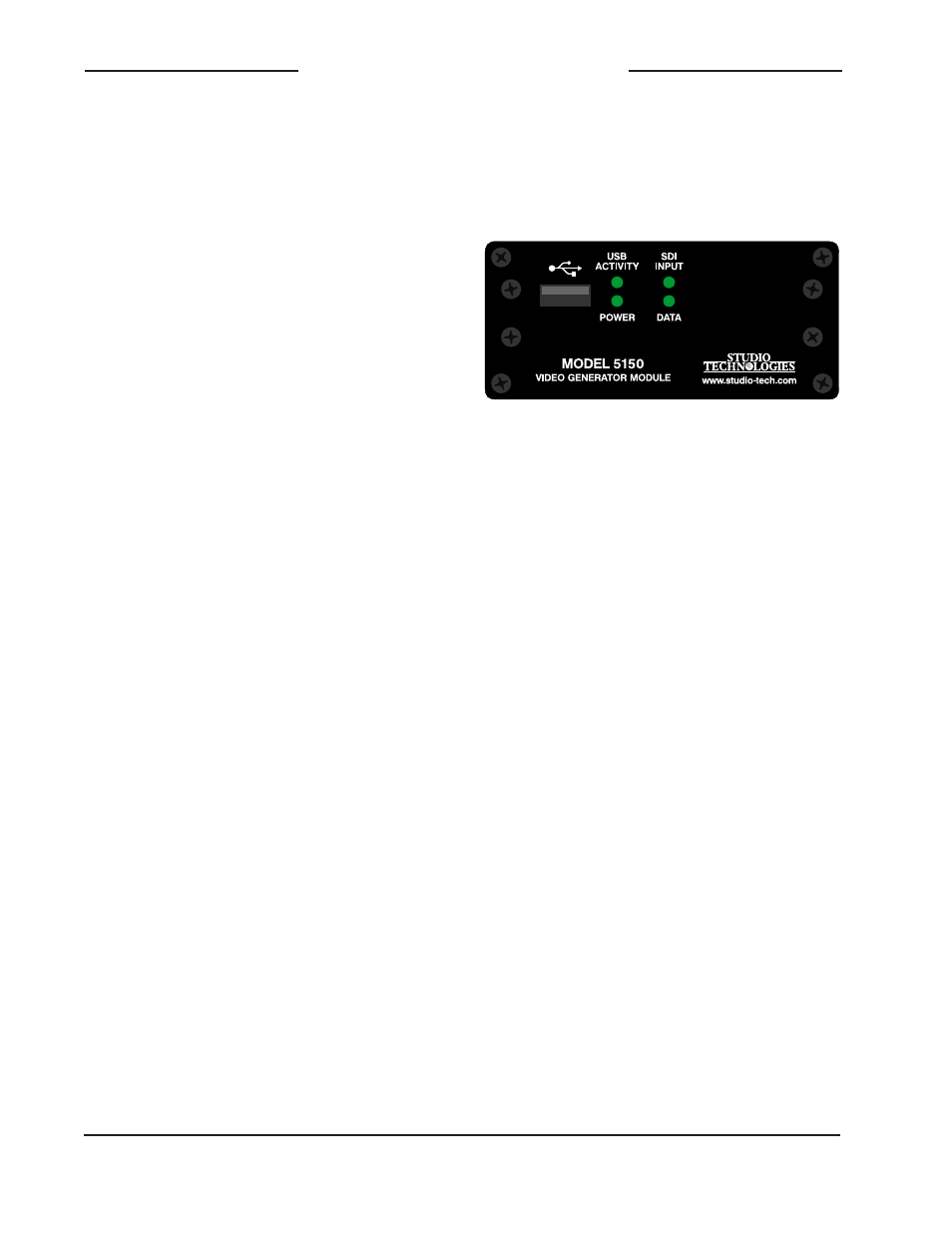
The USB Activity LED lights to represent the number 1
The SDI Input LED lights to represent the number 2
The Power LED lights to represent the number 3
The Data LED lights to represent the number 4
Figure 9. Detail of front panel showing how
the LEDs display the MCU and FPGA firmware
version numbers.