Coaxial (bnc) sdi output, Coaxial (bnc) sdi input – Studio Technologies 5150 V.1 User Manual
Page 9
Model 5150 User Guide
Issue 5, March 2014
Studio Technologies, Inc.
Page 9
Model 5150
Video Generator Module
wires are required to connect the module
to the data bus. GPI and GPO connections
are made using a 3-pin header. After all the
connections have been completed the mod-
ule can then be secured into the designated
mounting location.
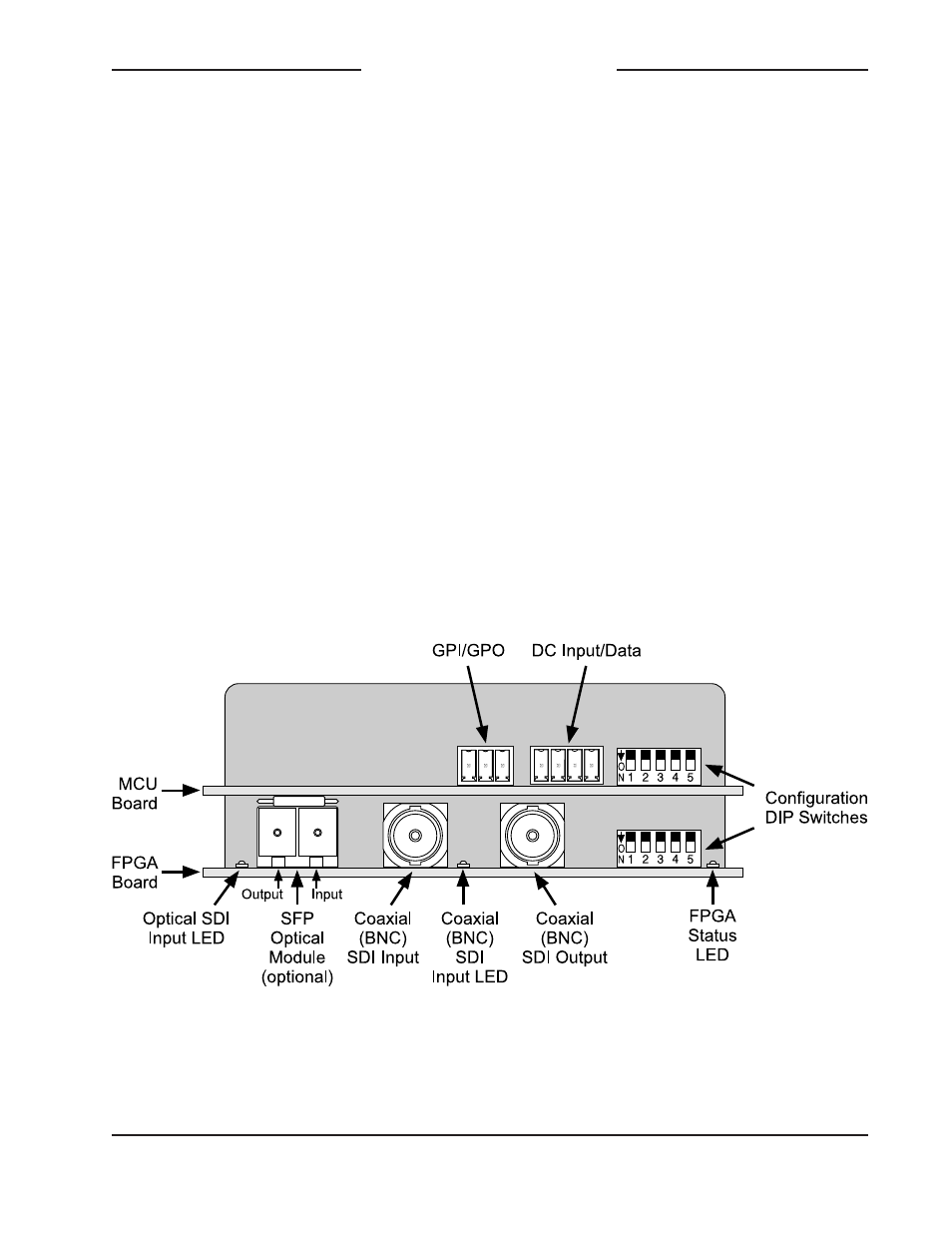
Coaxial (BNC) SDI Output
The Model 5150 provides an SDI output
that utilizes a broadcast-standard BNC
socket. This output is referred to as the
coaxial (BNC) SDI output. Refer to Figure 2
for a detailed view of the connector’s loca-
tion on the rear of the module. The coaxial
(BNC) output, depending on operating
conditions, will be either a SMPTE-
compliant HD-SDI (1.485 Gb/s nominal) or
a 3G-SDI (2.97 Gb/s nominal) signal. The
exact format/rate combinations supported
by the Model 5150 are listed in the Specifi-
cations section of this guide.
Coaxial (BNC) SDI Input
An SDI source can be connected to the
Model 5150 by way of a broadcast-stan-
dard BNC connector. This is referred to
as the coaxial (BNC) SDI input. Refer to
Figure 2 for a detailed view of the connec-
tor’s location on the rear of the module.
The coaxial (BNC) input is compatible
with SMPTE-compliant HD (1.485 Gb/s
nominal) and 3G (2.97 Gb/s nominal) SDI
signals. It is not compatible with standard
definition SD-SDI (270 Mb/s nominal) sig-
nals. The exact format/rate combinations
supported by the Model 5150 are listed in
the Specifications section of this guide.
A configuration setting must be made for
the coaxial (BNC) SDI input to be active.
Refer to the Configuration section of this
guide for details.
Figure 2. Detailed rear view of the Model 5150 Video Generator Module showing the MCU
and FPGA boards