Studio Technologies 42A 2013 User Manual
Page 21
Model 42A User Guide
Issue 2, December 2013
Studio Technologies, Inc.
Page 21
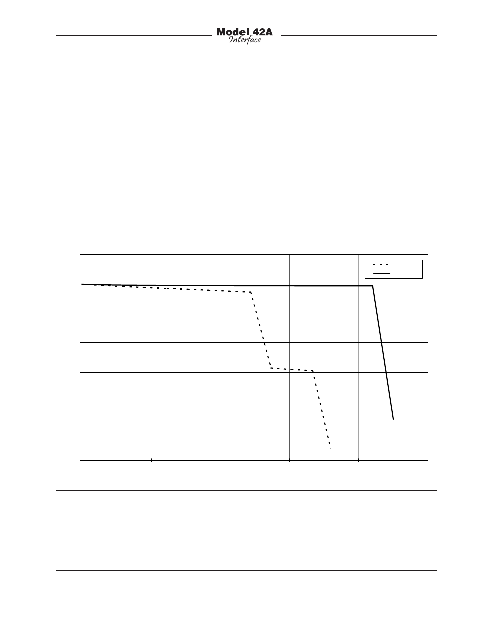
Figure 10. IFB output voltage-current curves for RTS 4000-Series and Model 42A Interface
0
5
10
15
20
25
30
35
0
50
100
150
200
250
Current (mA)
V
ol
ta
ge
(
V
)
4010
Model 41
Model 42A
this situation with the performance pro-
vided by the Model 42A. The DC voltage
supplied by its IFB outputs won’t “poop
out” when loaded over its 0 to 220 milliam-
peres range. This will allow IFB beltpack
and announcer’s console devices to func-
tion correctly in many more applications.
Figure 10 shows the IFB output voltage-
current curves for the RTS 4000-series and
the Model 42A Interface. The performance
differences are quite interesting.
It’s interesting to note the reason why
typical IFB output audio quality is less
than pristine. It’s not hard to notice the
background “hiss” that is always present
on pin 2 (DC with channel 1 audio) of the
interface connector. Technically, it’s white
noise that comes from the adjustable
voltage regulator being used as an “AM”
modulator and current limiter. The noise
is an artifact of the design topology and
simply can’t be overcome. How does
Studio Technologies know this? Because
our first “breadboard” designs used this
method and achieved the same poor
results! Only after the problem came
to light did work on an improved circuit
begin. The results were worth the effort.