Audio monitoring – Studio Technologies 42A 2013 User Manual
Page 14
Issue 2, December 2013
Model 42A User Guide
Page 14
Studio Technologies, Inc.
firmware. This combination adds “smarts”
to otherwise fairly pedestrian functions.
Using four electromechanical relays, the
audio monitor section accesses the IFB
outputs directly on pins 2 and 3 of their
respective output connector. This ensures
that the impact of the actual wiring and
connected user devices is monitored,
rather than just observing something
internal to the Model 42A’s circuitry. Pin 2
of each of the four IFB output connectors
(one connector on the front panel and one
on the back) is also connected, by way of
interface circuitry, to analog-to-digital con-
verter inputs on the processor. This allows
the DC output voltages to be continuously
monitored.
Associated with the audio and DC voltage
monitor functions are four status LEDs,
one pushbutton switch, two 5-segment
LED level meters, a rotary level control,
and a headphone jack. The four monitor
status LEDs are used to indicate which
IFB output is currently being audio moni-
tored as well as presenting the status of
the DC output voltages. One of the LEDs
is always lit, indicating which IFB output
is currently being monitored by the meters
and headphone output.
Audio Monitoring
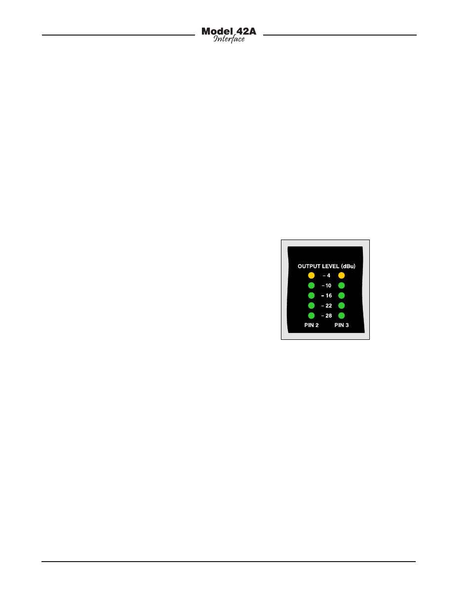
The dual 5-segment LED level meters al-
low a direct observation of the audio levels
present on pins 2 and 3 of the selected
IFB output’s 3-pin XLR connector pair. In
television broadcast settings, the Pin 2
(left) meter will typically display the “inter-
rupt” signal while the Pin 3 (right) meter
will display “program.” A quick glance at
the meters will give an accurate overall
indication of a circuit’s performance.
It’s important to note that the Model 42A’s
meters are calibrated differently from the
typical “VU” scale. The level steps were
selected to effectively display the IFB
output’s nominal –10 dBu signal level.
The ballistics of the meters are also differ-
ent, being a cross between VU and peak.
The bottom four LEDs are green in color
and indicate that signals are in the normal
range. The top LED, yellow in color, lights
when signals are 6 dB or greater above
–10 dBu. A correctly functioning IFB out-
put should find normal signals lighting the
four green LEDs with the yellow LED light-
ing only on peaks.
Figure 6. Detail of front panel showing dual
5-segment LED level meters
The headphone output allows audible
monitoring of the selected IFB output.
The 2-channel (stereo) output is compat-
ible with virtually any pair of stereo head-
phones. As the output circuitry meets
“pro audio” specifications, it’s recom-
mended that high-quality headphones be
used. Pin 2 of the IFB output is the signal
source for the left channel of the head-
phone output. Pin 3 of the IFB output is
the source for the right channel. The rotary
control adjusts the output level of both the
left and right channels. Should it be nec-
essary, there’s no reason why the head-
phone output couldn’t also be used as
a line-level monitor output.