Dc voltage monitoring – Studio Technologies 42A 2013 User Manual
Page 15
Model 42A User Guide
Issue 2, December 2013
Studio Technologies, Inc.
Page 15
A pushbutton switch, located on the front
panel, serves two purposes: selecting the
IFB output channel to be monitored and
enabling the auto scan feature. To select
an IFB output channel to be monitored,
press and release the IFB Circuit Select
pushbutton. Each press of the button
will advance the channel to be monitored
by one. A delay is built into the channel
selection process allowing a user to move,
for example, from channel 1 to channel 3.
By pressing the button twice in rapid
succession channel 2 will be automatically
skipped.
Unique to the Model 42A is its auto scan
feature. Pressing and holding the button
for two seconds will cause this feature to
begin operation. In this mode the monitor
source automatically “steps” through each
IFB output, pausing for eight seconds
before moving on to the next. Ideally, this
will allow technical personnel to observe
a problem through casual viewing of the
Model 42A’s front panel.
DC Voltage Monitoring
The Model 42A’s microcontroller inte-
grated circuit, under software control,
“watches” to ensure that the DC voltage
present on pin 2 of each IFB output con-
nector pair is at an acceptable level. The
low-voltage threshold for the Model 42A’s
30 volt DC output is 24 volts. As discussed
in the previous section, the four LED
indicators display which IFB channel is
currently selected for audio monitoring. In
addition, the LEDs provide an indication of
the DC voltage status on the IFB outputs.
An LED will “flash” at a moderate cadence
if the voltage on pin 2 of its associated IFB
output falls below the acceptable value.
This can be caused by a temporary over-
current or short-circuit condition, such
as when interconnecting user devices to
Model 42A IFB outputs using faulty por-
table cabling.
An under-voltage condition that’s pres-
ent for a continuous 4-second period will
cause a fault condition to be recognized.
The status LED associated with the prob-
lem IFB output channel will indicate this
condition by flashing at a faster rate. In
addition, the output voltage on that spe-
cific IFB output channel will automatically
shut down to an essentially off condition.
A 10-second “cool-down” period will then
take place, after which the output voltage
will again become active. As soon as the
output is enabled normal output voltage
monitoring will again take place. A con-
tinuous short-circuit presented to an
IFB output will result in a continuous
4-seconds-on/10-seconds-off error cycle.
Figure 7. Detail of front panel showing headphone
section
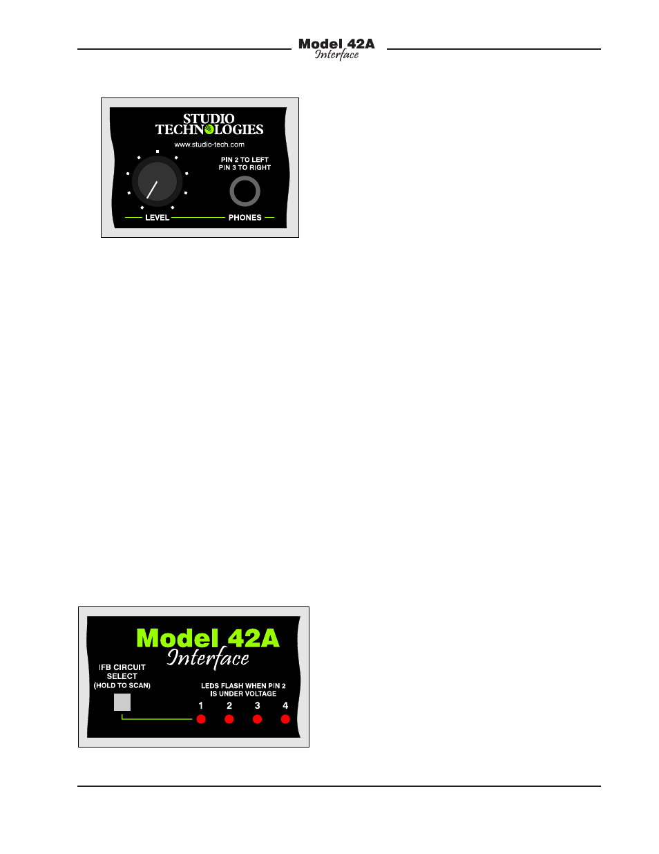
Figure 8. Detail of front panel showing four status
LEDs and associated pushbutton switch