Studio Technologies 42A 2013 User Manual
Page 11
Model 42A User Guide
Issue 2, December 2013
Studio Technologies, Inc.
Page 11
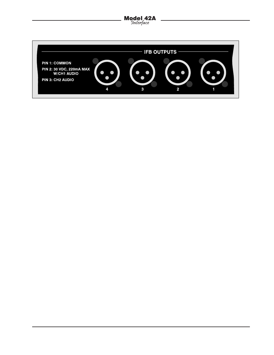
on pin 3 also has a nominal signal level of
–10 dBu. Its audio source is the channel 2
audio input associated with that specific
IFB output.
The Model 42A’s IFB outputs are interfaced
using eight 3-pin male XLR connectors; four
which are located on the unit’s back panel
and four on the front. They are organized
in groups of two connectors per IFB out-
put, one on the back panel and one on the
front. They are wired in parallel (“multed”)
and provide access to the identical signals.
The needs of the specific application will
dictate the manner in which the IFB output
connectors are used. For some applica-
tions, such as in fixed locations or produc-
tion trucks, it may be appropriate to utilize
only the connectors on the back panel. The
permanent interface cables, one for each
IFB output, must be terminated with 3-pin
female XLR connectors. It’s recommended
for this application that the IFB outputs be
wired by way of an input/output (I/O) con-
nector panel rather than directly to user de-
vices. It’s also a good idea for the I/O panel
to have “mults” (multiple connectors) for
each of the IFB outputs. For troubleshoot-
ing purposes it also may be useful to have
the IFB outputs pass through points on an
audio patch bay.
When a Model 42A is used in an equip-
ment rack that will move between broad-
cast events it may be desirable to not
permanently terminate any interconnect-
ing cables to the IFB output connectors.
In this way the front- and back-panel
connectors will remain available for show-
specific uses. For example, in a “booth
package” application the front-panel IFB
outputs will serve as a convenient point
to directly connect, using standard flex-
ible microphone cables, announcer’s
consoles, listen-only beltpacks, and other
user devices.
The type of interconnecting cables used
between the Model 42A’s IFB outputs and
the user devices will vary by application.
In a fixed installation it would be typical
to use 22 AWG, shielded, stranded cable
in either a single- or 2-pair configuration.
With single-pair cable, pin 1 should be
connected to shield and pins 2 and 3
connected to the cable pair. If 2-pair cable
is used, pin 1 should connect to one side
of each pair, with pin 2 going to one side
of pair one and pin 3 going to one side
of pair two. The shields can either go only
to the XLR connector shells, or to both the
connector shells and pin 1.
Shielding unbalanced audio signals can
be a tricky proposition. It is recommend-
ed that the focus be on using excellent
Figure 5. Detail of back panel showing IFB output connectors