Technical notes, Software revision number – Studio Technologies 41 2007 User Manual
Page 18
Issue 2, February 2007
Model 41 User Guide
Page 18
Studio Technologies, Inc.
Determining the actual IFB circuit current
draw won’t often be required but can be
useful in a tough troubleshooting situa-
tion. This measurement can be performed
using any good-quality digital multimeter.
Begin by setting the meter to measure
DC current. Then place the meter leads
in series with the pin 2 lead of the XLR-
type connector associated with the IFB
circuit to be tested. The easiest way to
measure the pin 2 current is to create a
simple adapter cable using one female
and one male 3-pin XLR-type connector.
Connect pin 1 on both connectors togeth-
er. Connect pin 3 on both connectors to-
gether. Connect separate wires to the pin
2 leads on both connectors. Then connect
the meter leads to these two wires. The
meter will indicate the DC current being
drawn while normal operation of the con-
nected device(s) takes place. Be certain to
connect the maximum number of devices
that might be powered by the IFB circuit.
That is, measure the worst-case condition
and ensure that the load is within the rated
200 milliamperes output. If possible, leav-
ing a 10 or 20% reserve margin is a good
practice.
Technical Notes
Software Revision Number
For Model 41 units with serial number 230
and later a special power-up sequence
allows the software version number to
be displayed. This is useful when work-
ing with factory personnel on applications
support and troubleshooting situations.
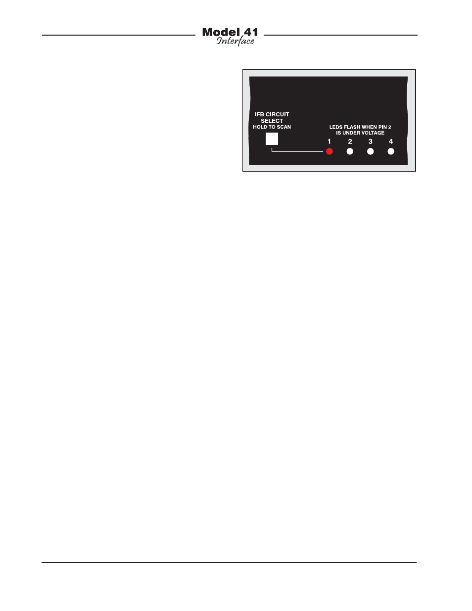
The four IFB circuit status LEDs are used
to display the software version number
with a range of 1 through 4. Refer to
Figure 9 for a detailed view of the LEDs
and the corresponding software version
numbering scheme. The Model 41’s initial
software release for hardware with serial
numbers 230 and later is version 1.1. This
is represented by the LED on the far left
side being lit.
To display the Model 41’s software ver-
sion is very simple. From the powered-
down state, press and hold the front-panel
pushbutton switch. Apply mains power
while continuing to press the button. The
normal power-up sequence will not oc-
cur but instead one of the status LEDs will
light. After the software version number
has been “read” the pushbutton can be
released. At this time the unit will begin its
normal power-up sequence.
Note that while it’s easy to determine
which software version is loaded into the
Model 41 a replacement microcontroller
integrated circuit is required to update it.
Contact the factory for details. Also, Model
41 units with serial numbers of less than
230 do no support display of their soft-
ware version. With these units applying
mains power will always cause the normal
power-up sequence to take place.
Figure 9. Detail of front panel showing the
status LEDs that display software version. In
this example, the software version is 1.1.