Post-installation, Audio input source level adjustment – Studio Technologies 41 2007 User Manual
Page 12
Issue 2, February 2007
Model 41 User Guide
Page 12
Studio Technologies, Inc.
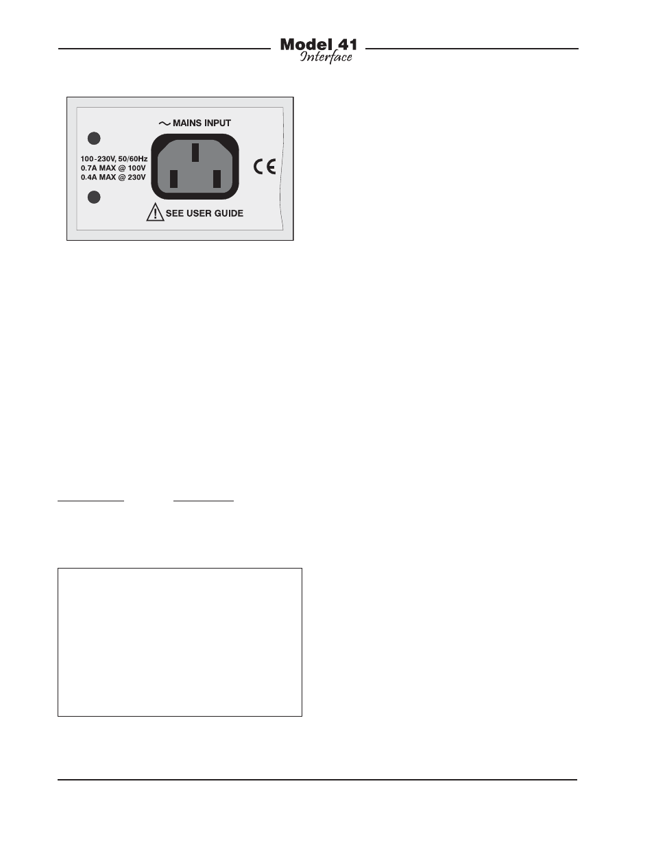
The Model 41 uses a 3-pin IEC 320 C14-
type inlet connector to mate with a de-
tachable mains cord. For units shipped to
North America and Japan a cord is sup-
plied that has a North-American (NEMA
15L) standard plug on one end and an
IEC 320 C13-type connector on the other.
Units bound for other destinations require
that the appropriate cord be obtained.
The wire colors in the mains cord must
conform to the internationally recognized
color code and should be terminated
accordingly:
Connection Wire
Color
Neutral (N)
Light Blue
Line (L)
Brown
Earth/Ground (E)
Green/Yellow
Safety Warning: The Model 41 does
not contain an AC mains disconnect
switch. As such, the AC mains cord
plug serves as the disconnection de-
vice. Safety considerations require that
the plug and associated inlet be easily
accessible to allow rapid disconnec-
tion of AC mains power should it prove
necessary.
As soon as AC mains power is applied
the Model 41 will begin its power-up se-
quence. As a “boot up” indication each of
the monitor section’s status LEDs will light
in an ascending order. After that has com-
pleted one of the status LEDs will remain
lit. The unit is now fully functional.
Post-Installation
Audio Input Source Level
Adjustment
It’s important to confirm and, if required,
adjust the level of the audio sources that
are connected to the Model 41’s inputs.
The monitor section’s dual 5-segment LED
level meters will help make this task sim-
ple. Begin by using the pushbutton switch,
located on the front panel, to select the
IFB circuit that is going to be calibrated.
Adjust the source levels so that the green
LEDs light when typical audio signals
are present. The desired nominal output
level of the IFB circuits is –10 dBu. This
is reflected in the top green LED being
calibrated to, and labeled, –10. The me-
ters’ yellow LEDs, labeled –4, should light
infrequently, generally only when signal
peaks are present. Achieving a precise
level calibration is not critical. But getting
the levels within the optimum range is very
important!
It’s likely that the initial levels provided by
analog ports on a digital matrix intercom
system won’t be an exact match with the
Model 41’s inputs. This shouldn’t pose a
problem as the computer control avail-
able on contemporary intercom sys-
tems should make level adjustment very
simple. From our research we found that
Figure 5. Detail of back panel showing AC
mains power connector