Daewoo VCR MECHANISM UNIT User Manual
Page 24
23
H.Adjustment of the wave form of DRUM Entrance
/ Exit (Fig. 5.8)
a. Connect the PT01 on the MAIN CIRCUIT BOARD with
a PATH ADJ.FIXTURE.
b. Play back an ALIGNMENT TAPE(DN-2 : MONO-
SCOPE signal)
c. Connect the S/W PULSE TEST PIN on the PATH ADJ.
FIXTURE with a CHANNEL-1 SCOPE PROBE.
d. Connect the VIDEO OUT on the MAIN CIRCUIT
BOARD with a CHANNEL-2 SCOPE PROBE(1V/div).
e. Turn the VR CONTROL on the PATH ADJ.FIXTURE
clockwise or counterclockwise until the signal shape of
ENVELOPE has the constant thickness.(Fig.5.8)
f. Adjust the S/T GUIDE ROLLER if the thickness of the
ENVELOPE signal is not uniform.
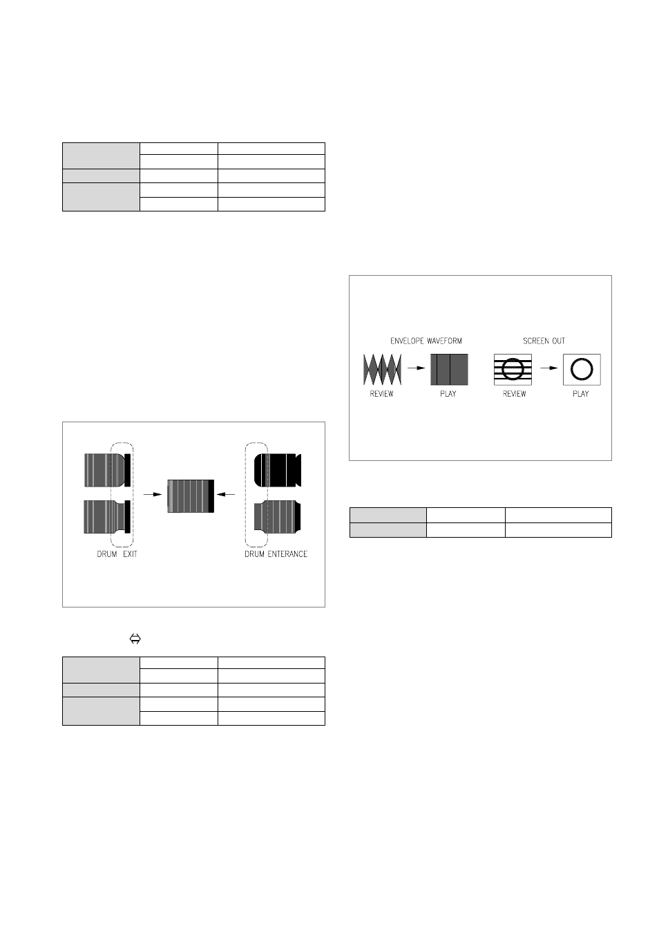
I. REVIEW PLAY(Fig.
5.9)
a. Connect the PT01 on the MAIN CIRCUIT BOARD with
a PATH ADJ.FIXTURE.
b. Play back an ALIGNMENT TAPE(DN-2 : MONO-
SCOPE signal)
c. Connect the S/W PULSE TEST PIN on the PATH
ADJ.FIXTURE with a CHANNEL-1 SCOPE PROBE.
d. Connect the VIDEO OUT on the MAIN CIRCUIT
BOARD with a CHANNEL-2 SCOPE PROBE(1V/div).
e. Make the VR CONTROL on the PATH ADJ.FIXTURE
to the center to maximize the ENVELOPE signal.
f. Play back the REVIEW MODE about 15 secong and alter
the mode to PLAY MODE.
g. Check whether the ENVELOPE waveform restore to its
original form within 3 second when the REVIEW mode is
changed to PLAY mode.
h. If the requirement of “g” is not satisfied, Check the run-
ning status of tape on the lower part of T GUIDE POST
and adjust the S/T GUIDE ROLLER precisely.
J. Checking for the J.AUDIO output waveform
(Adjustment of AC HEAD TILT & Height)
a. Connect the AUDIO output jack with an AUDIO LEVEL
METER.
b. Playback an Alignment Tape (DN-1:Color Bar 1KHz
Signal)
c. Check if the AUDIO output signal level is over -9~-
3dBm.
d. If the requirement of “c” is not satisfied, readjust the AC
HEAD TILT and the HEIGHT until the AUDIO output is
maximized. (Fig. 5.2, 5.3)
ADJUSTMENT OF THE TPAE TRANSPORTING SECTION. (CONTINUED)
S/W PULSE TEST PIN
PATH ADJ. FIXTURE
ENVELOPE TEST PIN
PATH ADJ.FIXTURE
Measurement Equipment OSILLOSCOPE
VR CONTROL
PATH ADJ.FIXTURE
S/T GHIDE ROLLER
TAPE TRANSMISSON SECTION
Test Point
Adjustment
FIg.5.8 Fine adjustment of the ENVELOPE at the DRUM
ENTRANCE/EXIT
S/W PULSE TEST PIN
PATH ADJ. FIXTURE
ENVELOPE TEST PIN
PATH ADJ.FIXTURE
Measurement Equipment OSILLOSCOPE
VR CONTROL
PATH ADJ.FIXTURE
S/T GHIDE ROLLER
TAPE TRANSMISSON SECTION
Test Point
Adjustment
FIg.5.9 Waveform change when the mode altered
(REVIEW
↔PLAY)
AUDIO OUTPUT
AUDIO OUTPUT JACK
AUDIO LEVEL METER
Test Point
Measurement Equipment