Adjustments – Smithco Diesel Super Rake 17-001-B (sn 2564 – 2620) Parts & Service Manual User Manual
Page 11
9
Service
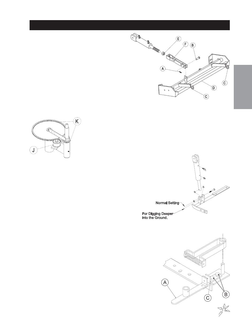
ADJUSTMENTS
RAKE LIFT CYLINDER
Completely lower Rake Lift. Remove cotter pin (A) and
clevis pin (B). Place attachment lift arms (C) at
1
/
16
"
above cross member (D) on Rake Lift. Loosen jam nut (E).
Twist cylinder extension (F) so clevis pin end of cylinder exten-
sion lines up with holes in attachment lift arm. Replace clevis and
cotter pins. Tighten jam nut. Raise and lower Rake Lift to check for
proper clearance.
PARK BRAKE
By turning knob on end of lever you can tighten or loosen brake a small amount. If this is not enough turn clevis
on brake cable to adjust length of cable.
STEERING CHAIN
Steering sprockets (K) should be level with each other, check with straight edge.
Make any adjustments. Slide idler pulley (J) so that it is snug onto the chain.
Tighten all nuts and bolts in place.
LIFT ASSEMBLY
When it is necessary to have attachment lift dig deeper or
lower into ground, relocate cylinder rod of hydraulic cylin-
der which controls the lift distances, into lower set of holes
in attachment lift swing arm. This new position forces at-
tachment farther down.
WHEEL ‘CREEP’ ADJUSTMENT
‘Creep’ is when engine is running and hydrostatic transmission is in
neutral, but due to inadequate alignment wheels still move. Do the fol-
lowing procedures to stop this motion.
1. Lift up and support machine so all wheels are off the ground and
can turn freely.
2. At rear of machine, on the bottom of the hydrostatic transmission
is the shift arm (A). Loosen bolts (B).
3. With engine running move stop (C) so it moves shift arm (A) to
center and wheel creep stops.
4. Tighten all fasteners and test by using foot pedal linkage to see
that the "creep" is removed.
5. Turn engine off and lower machine.