Important, Notice, Calculating the Page 8: Copyright 2011 smart-avi, all rights reserved, Technical specifications, Esolutions, Input/output signal, Suppo te the inte nal i configu atio n, Resolution refresh rate
Page 8: Copyright 2011 smart-avi, all rights reserved, Technical specifications, Esolutions, Input/output signal, Suppo te the inte nal i configu atio n, Resolution refresh rate
14
15
www.smartavi.com
www.smartavi.com
5) To query crosspoints from PC:
//FxxU
• If all outputs are connected to input 1 then a 4x4 Matrix will respond
with
<0x80><0x80><0x80><0x80>
• The router will send back one byte for each output and the string
ends with a
above, since there are 5 bytes total, we know that there are 4
outputs.
• To calculate the input number, the router sends the input number
with the 7th bit set.
0x80 = “1000 0000” input 0
0x81 = “1000 0001” input 1
…
0x8F “1000 1111” input 15
Notes:
When successful, commands #1-4 will acknowledge by sending the
checksum with nibbles swapped &
e.g. checksum of 0x24 acknowledges with <0x42>
All bytes in examples are Ascii characters unless they are contained in brackets <>
•
•
•
• xx is the frame address of the router e.g. “00” or “01”
o From the factory the address is always “00”, however it can be changed with
command #4
• yy is the Output (monitor) number. e.g. “01”
• zz is the Input number. e.g. “06” or “16”
• nn is the Matrix’s new frame address
calculated by performing an XOR of the full com-
mand string. For example: //F00M12I03 will XOR
to the hexadecimal value 0x42, therefore the value
of
CALCULATING THE
IMPORTANT
© Copyright 2011 Smart-AVI, All Rights Reserved
NOTICE
The information contained in this document is subject to change without notice.
Smart-AVI makes no warranty of any kind with regard to this material, including but not
limited to, implied warranties of merchantability and fitness for any particular purpose.
Smart-AVI will not be liable for errors contained herein or for incidental or consequential
damages in connection with the furnishing, performance or use of this material.
No part of this document may be photocopied, reproduced or translated into another
language without prior written consent from Smart-AVI.
For more information, visit www.smartavi.com.
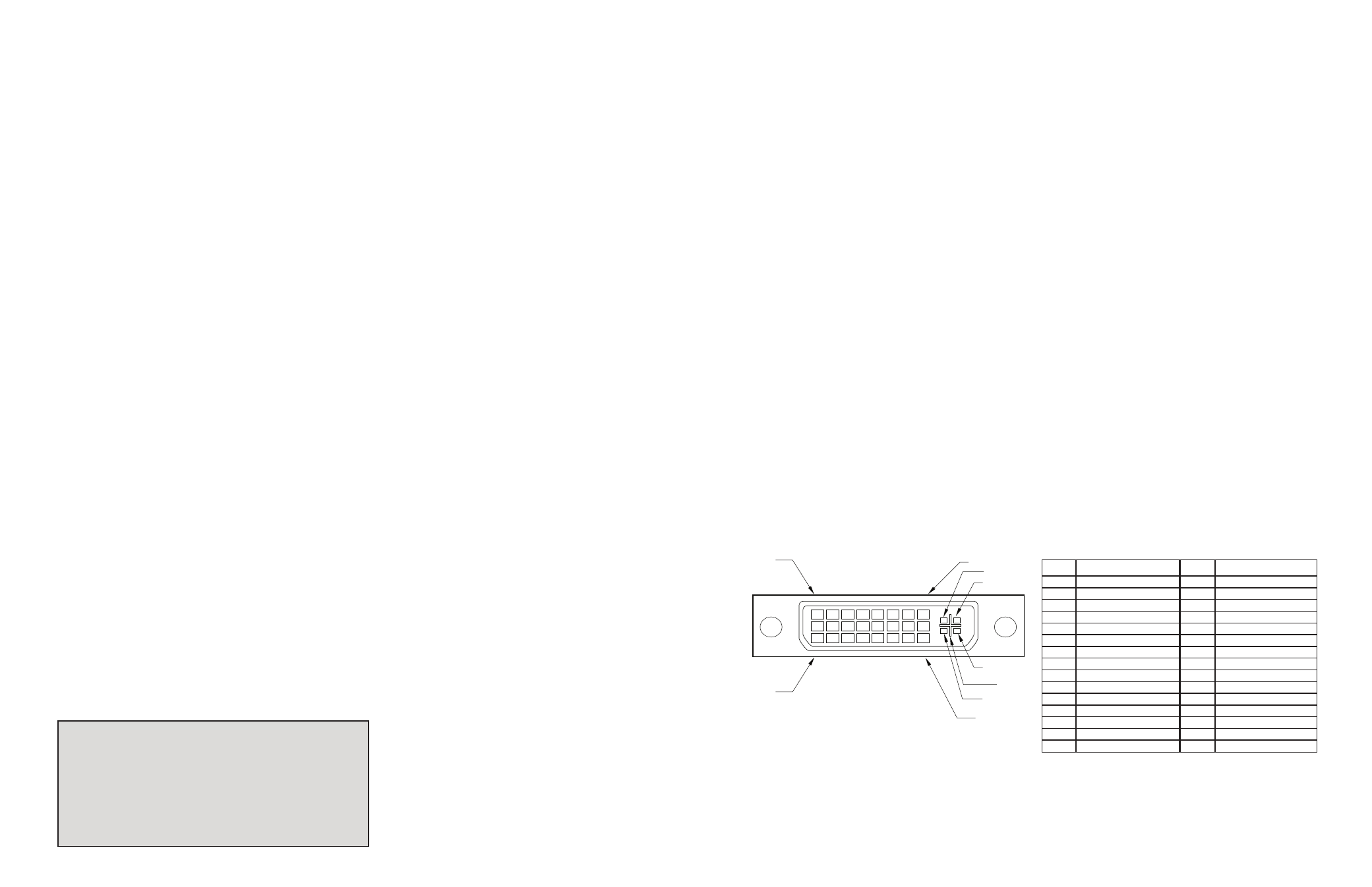
Technical Specifications
Input/Output Signal
#
n
i
P
l
a
n
g
i
S
#
n
i
P
l
a
n
g
i
S
1
-
2
a
t
a
D
S
.
D
.
M
.
6
T
1
t
c
e
t
e
D
g
u
l
P
t
o
H
2
+
2
a
t
a
D
S
.
D
.
M
.
7
T
1
-
0
a
t
a
D
S
.
D
.
M
.
T
d
3
l
e
i
h
S
4
/
2
a
t
a
D
S
.
D
.
M
.
8
T
1
+
0
a
t
a
D
S
.
D
.
M
.
T
4
-
4
a
t
a
D
S
.
D
.
M
.
9
T
d
1
l
e
i
h
S
5
/
0
a
t
a
D
S
.
D
.
M
.
T
5
+
4
a
t
a
D
S
.
D
.
M
.
0
T
2
-
5
a
t
a
D
S
.
D
.
M
.
T
6
k
c
o
l
C
C
D
1
D
2
+
5
a
t
a
D
S
.
D
.
M
.
T
7
a
t
a
D
C
D
2
D
d
2
l
e
i
h
S
k
c
o
l
C
S
.
D
.
M
.
T
8
c
n
y
S
.t
r
e
V
g
o
l
a
n
3
A
2
+
k
c
o
l
C
S
.
D
.
M
.
T
9
-
1
a
t
a
D
S
.
D
.
M
.
4
T
2
-
k
c
o
l
C
S
.
D
.
M
.
T
0
1
+
1
a
t
a
D
S
.
D
.
M
.
T
1
d
1
l
e
i
h
S
3
/
1
a
t
a
D
S
.
D
.
M
.
1
T
C
d
e
R
g
o
l
a
n
A
2
1
-
3
a
t
a
D
S
.
D
.
M
.
2
T
C
n
e
e
r
G
g
o
l
a
n
A
3
1
+
3
a
t
a
D
S
.
D
.
M
.
3
T
C
e
u
l
B
g
o
l
a
n
A
4
1
r
e
w
o
P
V
5
4
+
C
c
n
y
S
z
r
o
H
g
o
l
a
n
A
5
1
D
N
5
G
C
d
n
u
o
r
G
g
o
l
a
n
A
PIN 17
PIN 1
PIN 24
PIN 8
C 4
C 1
C 2
C 5
C 3
esolutions
Suppo te
the inte nal
I configu atio
n
z
H
5
8
0
8
4
x
0
4
6
z
H
5
8
0
0
6
x
0
0
8
z
H
5
8
8
6
7
x
4
2
0
1
z
H
5
7
0
7
8
x
2
5
1
1
z
H
5
7
8
6
7
x
0
8
2
1
z
H
0
6
0
6
9
x
0
8
2
1
z
H
0
6
4
2
0
1
x
0
8
2
1
z
H
0
6
0
0
2
1
x
0
0
6
1
Resolution
Refresh Rate
5
C
1 6