Skutt EnviroVent 2 User Manual
Page 7
7
7
s
eTup
S
tEp
5 - i
nStalling
thE
plEnum
cup
and
Spring
Stand
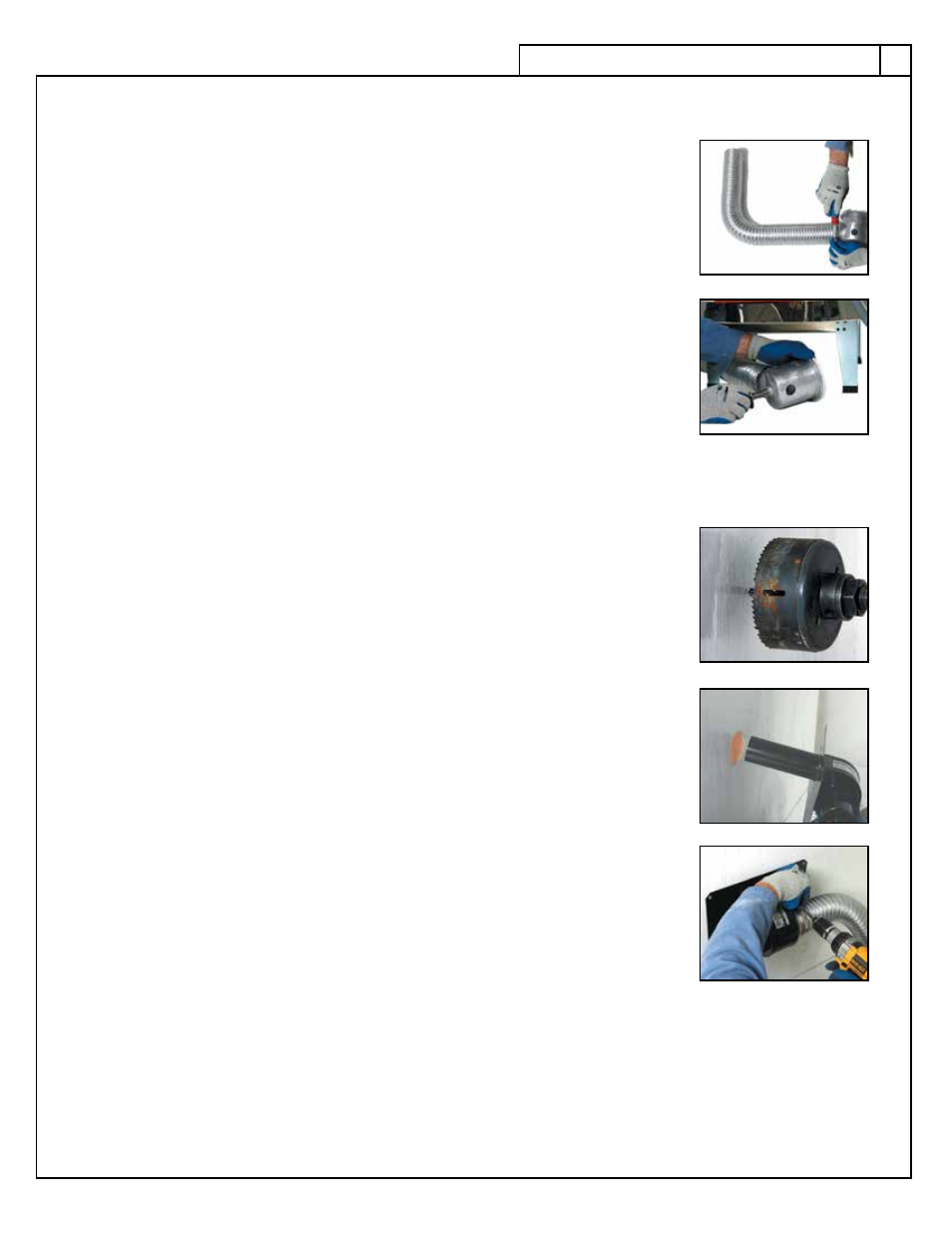
• Using gloves to protect your hands, stretch the flex tubing to the proper length for
your installation. Stretch out the last 3” of tubing on each end of the duct to ensure
they are wide enought to fit over their connections. Be careful not to collapse the
open end of the flex tubing. You should be able to stretch the flex tubing 6 ft. to 8 ft.
• Attach the length of 3” diameter aluminum flex tubing to the 3” sleeve on the ple-
num cup and secure with the hose clamp.
• Place the spring over the plenum cup stand post and insert the 7/16” stand post
into the small hole in the bottom of the aluminum plenum cup. Refer to the instal-
lation drawing if necessary. When properly assembled the plenum stand should be
spring loaded into the bottom of the plenum cup.
• Place the plenum cup and stand under the holes drilled in the kiln floor by rotat-
ing the cup horizontally, compressing the spring to permit cup rotation to vertical
and releasing the spring tension. Ensure that the plenum cup is centered under the
holes in the kiln’s floor.
S
tEp
6 - i
nStalling
thE
blowEr
and
motor
aSSEmbly
• Locate a spot on the wall to mount the blower assembly and discharge tube. Im-
portant: Choose a spot that is close enough for the aluminum flex tubing to reach.
Remember that most kilns must be a minimum of 18” from the wall. If possible,
locate a spot that allows you to mount the vertical edge of the mounting plate into
a wall stud or ceiling joist. If you need to go further then the ducting will allow
consult the Custom Installation section of this manual.
• Drill a 3 1/8” clearance hole in the wall or ceiling to accept the 3” diameter dis-
charge pipe. Be sure to check for wires and pipes in the wall prior to drilling.
• Insert the discharge pipe through the 3 1/8” hole and fasten the mounting plate in
place using the supplied sheet metal screws or toggle bolts. Choose the proper fas-
tener for your wall type of material. If you are using the toggle bolts you will need
to position the mounting plate and mark where the holes will be. Predrill the holes
for the toggle bolts using a 3/8” drill bit . The 3” metal discharge tube is supplied
at 8” in length. This tube may be trimmed shorter or added to in order to allow for
any installation.
• Attach the open end of the aluminum flex tube to the blower inlet flange using the
hose clamp provided. Check the plenum cup assembly to make sure it has not
shifted out of place.
• We recommend attaching a hood with a screen over the end of the discharge tube.
This will help prevent snow, rain or debris from entering into the discharge tube
or blocking the air flow. The screen is also important to prevent small animals and
insects from entering the tube. This item is not included with the kit but can usually
be found at local hardware stores.
f
loor
m
ountEd
v
EntS
A bolt-on plate comes with your kit and allows you to place the vent motor on the floor when wall-mounting
is not possible. To install, just bolt the floor plate onto the bottom lip of the mounting plate using the hardware
included in the kit. This allows the motor to sit upright on the floor. Install ducting to the discharge tube and
vent it as you would a dryer making sure all joints are airtight. When the vent is floor mounted it is no longer a
negative pressure system.