3 installation – Sim2 HT200 DMF User Manual
Page 6
6
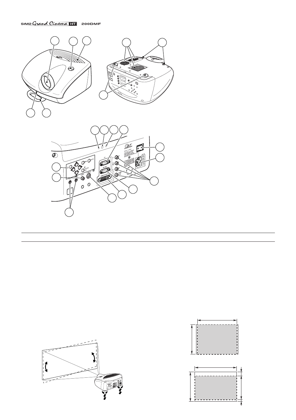
1
Projection lens
2
Lens shift knob.
3
Cooling air inlet vents.
4
Remote control IR sensor.
5
Cooling air outlet vents.
6
Adjustable carry-handle.
7
Adjustable levelling feet.
8
Ceiling/wall bracket fixing holes.
9
Fused power socket.
10
Main power switch.
11
Remote control rear IR sensor.
12
Green LED.
13
Red LED.
14
Rear keyboard pad.
15
Composite video input.
16
S-Video input.
17
VGA input.
18
RGB / YCrCb input.
19
12Vdc screen output.
20
RS232 interface connector.
21
Remote Input Interface EVC
connector.
3 INSTALLATION
Position the projector the desired distance from the screen: the
size of the projected image is determined by the distance from
the lens of the projector to the screen, the zoom setting and the
operating mode. See “Appendix B”: Projection distances” for
more information.
The projector has two different operating modes: 4:3 mode (dis-
played image has 800x600 active pixels) and 16:9 mode
(848x480 active pixels).
The higher horizontal resolution in the 16:9 mode makes the
projected image slightly wider than the 4:3 mode image
(Fig. 7)
.
800
600
800x600 pixel
(4:3 mode)
848
600
480
80
40
848x480 pixel
(16:9 mode)
Position the projector on a stable, suitable platform or utilise
the optional bracket for a fixed ceiling or wall installation.
CAUTION: In the case of ceiling or wall mounting using a
suspension bracket, follow the instructions carefully and
comply with the safety standards you will find in the box
together with the bracket. If you use a bracket different to
the one supplied by SIM2 Multimedia, you must make sure
that the projector is at least 65 mm (2-9/16 inch) from the
ceiling and that the bracket is not obstructing the air vents
on the lid and on the bottom of the projector.
Adjust the feet underneath to obtain a level position, lining up
the base of the projected image to the base of the projection
screen
(Fig. 6)
.
Fig. 6
Fig. 7
6
4
1
2
3
5
8
7
12 11 13 17
9
10
18
20
21
16
19
15
14