Sierra Video Sequoia Family User Manual
Page 19
INSTALLATION
13
Control Port 1 (by default the Terminal Port)
This port can be either RS-232 or RS-422 using a 9 pin D connection. RS-232 operation requires
the router to be configured as a DCE (Pin 2 TX, Pin 3 Rx, Pin 1, 9 GND) device with a PC being a
DTE device.
Control Port 2 (by default the Host Port)
This ports can be either RS-232 or RS-422 using a 9 pin D connection. RS-232 operation
requires the router to be configured as a DCE (Pin 2 TX, Pin 3 Rx, Pin 1, 9 GND) device with a
PC being a DTE device.
Control Port 3
This port can be either RS-422 or RS-485 using a 9 pin D connection.
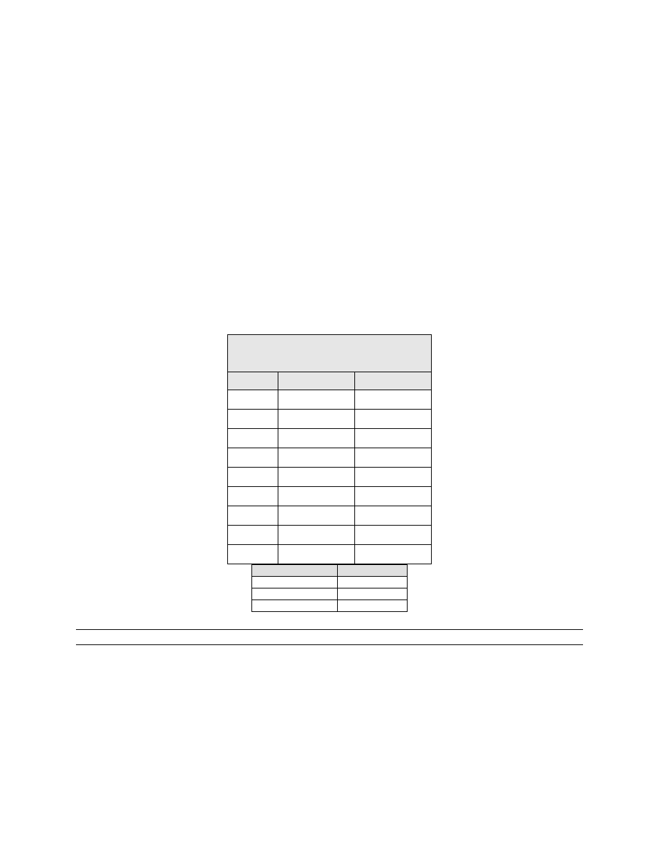
Connections to the 9-pin are shown in the table below. “Transmit” and “Receive” are names used
by the Sierra Video Systems router. For connection to an external PC or other controlling device
use the opposite names.
PC
RTR
2 RX
2 TX
3 TX
3 RX
5 GND
1 , 9 GND
NOTE:
To convert the 9-pin connector to an RS422 serial port, move the jumpers on JP-3 (for port 1) or JP-4 (for
port 2) as indicated by the silk screen on the control processor board.
Host & Terminal Port
Installation
Pin
RS-232
RS-422
1 Ground Ground
2 Transmit
Transmit
(-)
3 Receive
Receive
(+)
4
Not used
Not used
5
Not used
Not used
6
Not used
Not used
7
Not used
Transmit (+)
8
Not Used
Receive (-)
9 Ground
Ground