Connecting to video devices, Connecting peripherals, Control system connections – Sierra Video Sequoia Family User Manual
Page 18: Serial control ports
SIERRA VIDEO SYSTEMS
12
Connecting To Video Devices
Video input and output devices (such as monitors or recorders) may be connected to the routing
switchers through the BNC type connectors located on the back of the unit. Keep in mind that the
output signal format will be the same as the input signal.
All signal connections that use more than one cable interconnecting between devices should be
of equal timing length (example: cables between a camera and the switcher should have the
same time delay).
Unused outputs do not need to be terminated.
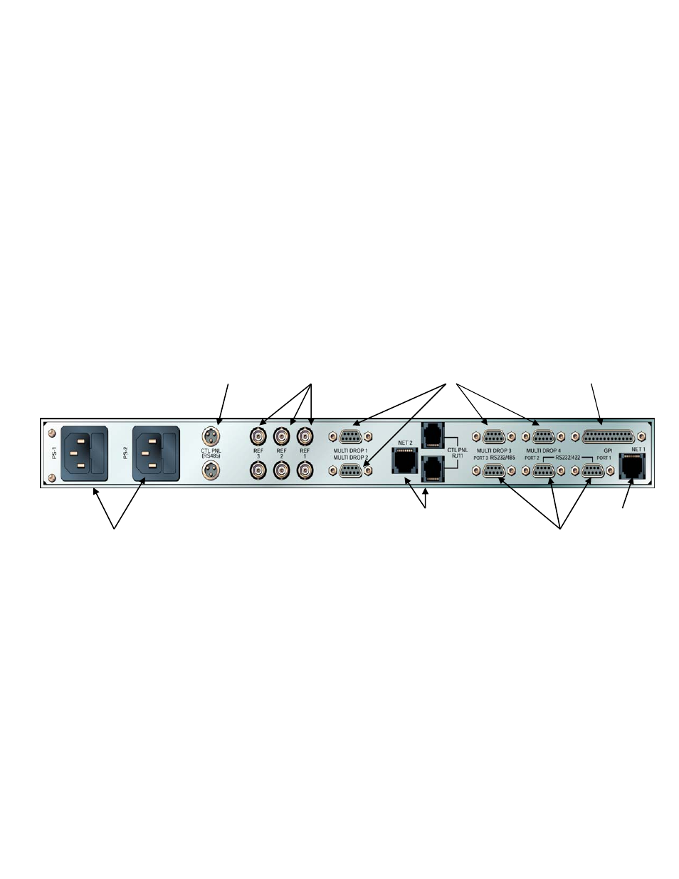
Connecting Peripherals
Control panels, sync inputs, and power are all connected to the rear of the processor frame. The
peripherals area may vary depending on the model size and type.
Control System Connections
Connectors associated with the system's internal control computer are located on the rear of the
Processor frame.
The following section only pertains to the 1 RU Control Processor frame.
Serial Control Ports
The internal control computer has three serial control ports. Each has a separate purpose.
Control Panel
Connectors
(Looped)
Video Sync
Referencing
Inputs (Looped)
Future Use
Future Use
AC Power
Connection
And Fuse
GPI I/O Connector
Multi-frame
interconnect
RS-232/422 Serial
Control Connectors