1 external relay racks – Sensoray 2410 User Manual
Page 8
2410 Instruction Manual
6
Digital I/O Interface
4.2.1 External Relay Racks
The DIO connector pinout is compatible with a variety of solid
state relay racks (e.g., SSR-RACK08, SSR-RACK24 and
SSR-RACK48). However, there is no universal standard pinout
for relay racks, so before purchasing a rack you should verify
that it has a compatible pinout.
Most SSR racks include a terminal block, a Molex connector,
or both to connect 5VDC power to the rack. The 2410 module
provides 5VDC for this purpose on its AUX power connector
(see Figure 2).
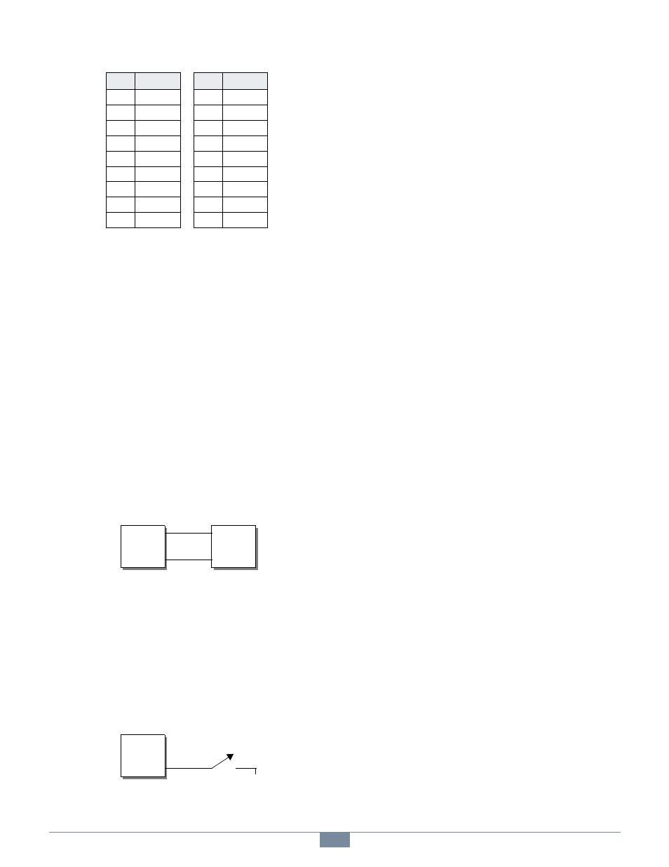
4.2.2 Sensoray 2410TA Termination Board
On the 2410TA board, each DIO has two terminal block
connections: the active-low DIO signal (marked “-”) and +5V
(marked “+”). When a channel is functioning as an output,
these two terminals may be connected to a load as shown in
Figure 4.
Figure 4: Recommended Output Wiring
The load impedance must be high enough to limit DIO current
to its maximum allowed value. See page 7 for details.
If the load is inductive (e.g., a mechanical relay), a protection
diode should be added across the load to suppress induced
EMF that might otherwise damage the DIO circuitry.
When a channel is operating as an input (e.g., hard contact), the
active-low input signal is connected as shown in Figure 5.
Figure 5: Recommended Input Wiring
17
DIO47
42
DIO22
18
DIO46
43
DIO21
19
DIO45
44
DIO20
20
DIO44
45
DIO19
21
DIO43
46
DIO18
22
DIO42
47
DIO17
23
DIO41
48
DIO16
24
DIO40
49
NC
25
DIO7
50
GND
Table 3: DIO Connector Pinout
Pin
Signal
Pin
Signal
+
-
2410TA
+
-
Load
+
-
2410TA
NC
GND