4 safety features, 5 connectors, 6 power connections – Sensoray 2410 User Manual
Page 5: 7 ethernet connection
2410 Instruction Manual
3
Introduction
2.4 Safety Features
Model 2410 features special mechanisms that can be used to
enhance the safety of application systems:
• A hardware watchdog timer forces a hardware reset in the
event of a malfunction by the module’s internal CPU, thus
forcing all digital outputs to their inactive (high) states.
• A communication watchdog timer generates a software
reset if a network client ceases to communicate. This can
optionally reset all outputs to their inactive states.
2.5 Connectors
All connectors have mechanical detentes or provision for
hold-downs to help maintain connections in high-vibration
environments.
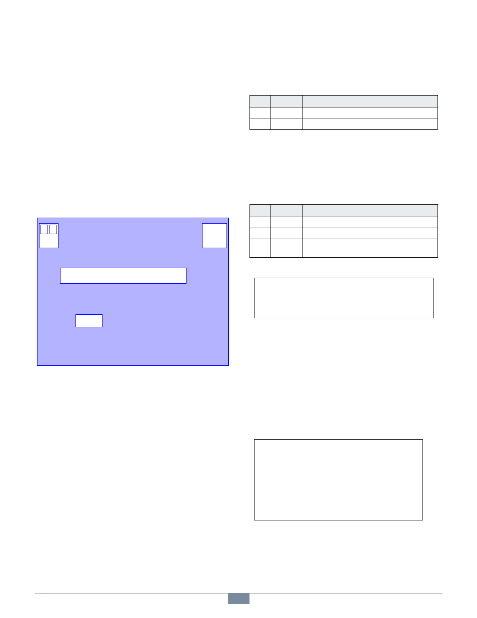
Figure 2: Module Layout
The connectors shown in Figure 2 have these functions:
• AUX — Auxiliary 5VDC output power for relay racks.
• DIO — General purpose digital I/O channels.
• ETH — Ethernet interface.
• TB — 24VDC input power terminal block.
Several connectors are reserved for manufacturing and test.
Applications should not make electrical connections to these
connectors: P1, JP2. A shunt must be installed at JP1 for
normal operation.
2.6 Power Connections
Module input power must be connected to the terminal block
labeled “TB” in Figure 2.
Auxiliary 5VDC output power is available from the AUX
connector (see Figure 2). This can be used to supply limited
auxiliary power to external relay racks or other low current
loads that require 5VDC power. See Chapter 5 for the electrical
specifications for this circuit.
2.7 Ethernet Connection
An RJ-45 jack (ETH connector in Figure 2) interfaces the
module to a 10BaseT/100BaseTX Ethernet network. A
Category-5 (or better) shielded or unshielded twisted pair (STP
or UTP) patch cable—which is not supplied with the module—
must be plugged into this jack.
Use a standard patch cable if you are connecting the module to
a switch, hub or router. Use a crossover cable if the module
will be directly connected to a dedicated Ethernet client.
ETH
DIO
1
AUX
1
+
-
TB
1
Table 1: Terminal Block Pinout
Pin
Name
Function
1
+24V
+24VDC module power.
2
GND
Return for the +24VDC signal on pin 1.
Table 2: Auxiliary Power Output Connector Pinout
Pin
Name
Function
1
+5V
+5V output power.
2, 3
GND
Return for the +5V signal on pin 1.
4
NC
No connect. This pin makes no electrical connection
to the module’s circuitry.
PWR lights continuously when 24VDC power is
applied and the module’s internal power supply
is operating.
Two LEDs are located near the ETH connector:
LNK lights continuously when incoming link
pulses are detected.
ACT lights briefly when incoming Ethernet
packets are detected.