6 edge capture flag register (channels 0-63), 7 clearing captured edges – Sensoray 621 User Manual
Page 9
Sensoray Model 621/721 Instruction Manual
Page 7
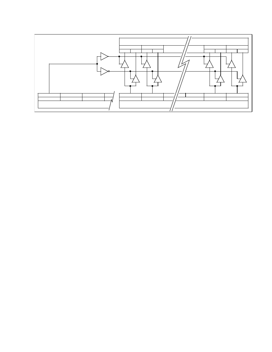
A relay channel must be "armed" before it will capture a detected edge.
An internal ARM Capture register is used to arm or disarm edge capturing. A “1” in the corresponding
channel position will allow edge capturing while a “0” will disable edge capturing on that channel.
The host system does not have direct access to this register. It is written to using the ARM Control register and
the “ARM” bit of the “Data direction/Misc./Status” register.
If ARM bit = “1”:
All channels whose corresponding bit in the ARM Control register is a “1” are
armed. Those channels with a “0” in the ARM Control register remain unchanged.
If ARM bit = “0”:
All channels whose corresponding bit in the ARM Control register is a “1” are
disarmed. Those channels with a “0” in the ARM Control register remain
unchanged.
See Figure 2 for a diagram of the process.
Reading the “ARM Control” register accesses the internal ARM Capture register directly and will give
the current status of the register. A “0” means that channel is disabled while a “1” shows it is armed.
If a channel is armed for edge capture and the same channel is set for output, a change in output level
could result in a captured event. Unless you want a “loop-back” event, a channel set for output should
have capturing disabled.
5.2.6 Edge Capture Flag Register (channels 0-63)
Each channel is associated with a one-bit capture register. The capture register is responsible for logging
the occurrence of a detected edge. When a selected edge occurs while capture is enabled, the associated
capture flag is set. All of the capture flags can be read through the edge capture flag port.
Note: before the capture register can log a detected edge, the channels capture register must be armed.
After capturing an edge, the capture register remains set until explicitly reset (cleared) by the host.
5.2.7 Clearing Captured Edges
Sometime after a captured edge is detected, it is necessary to reset the associated capture register. This is
accomplished by disarming the associated “arm capture” register.
Set
Reset
Set Reset
Bit 0
Bit 1
Reset
Set
Bit 30
Bit 31
Reset
Set
Internal ARM Capture Register
Bit 31
Bit 30
Bit 0
Bit 1
Internal ARM Control Register
Bit 14
Bit 15
Data Direction/Misc./Status Register
Bit 13
ARM
X
X
Channel 31
Channel 30
Channel 1
Channel 0
Figure 2