Seaward AGL-5 User Manual
Page 2
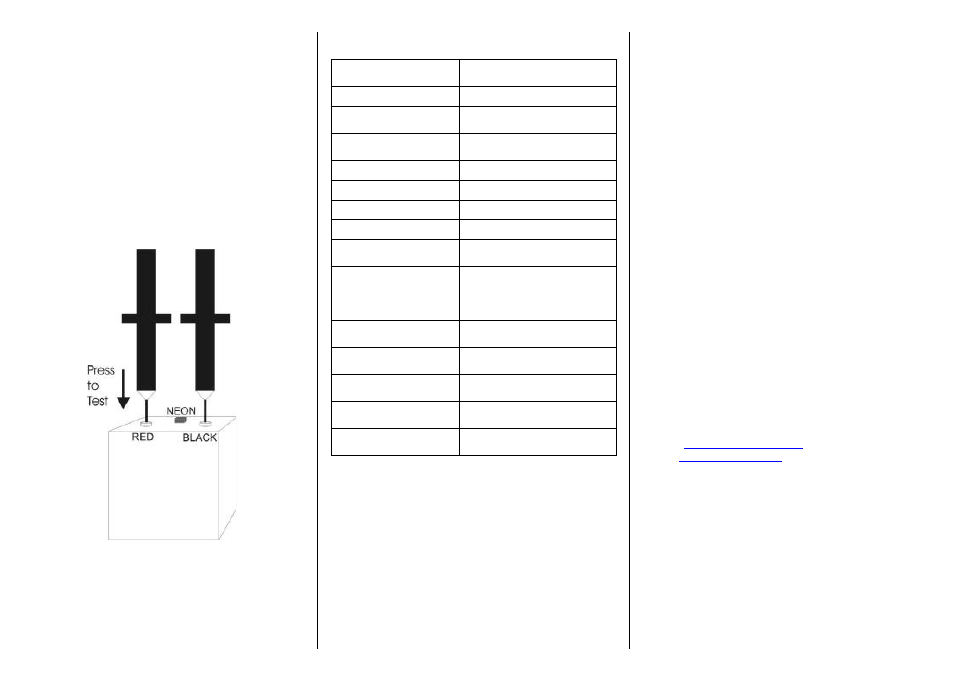
2 Proving
•
Connect the one probe to the BLACK
terminal.
•
Connect the other probe to the RED terminal.
•
Press the probe down onto the RED terminal
as shown below to operate the internal
micro-switch.
•
Confirm that the neon illuminates indicating
the test voltage is active.
•
Confirm that the LED indicators in the AGL-5
illuminate.
•
Disconnect both probes from the proving
unit.
3 Specifications
Maximum Working
Voltage
5000V AC/DC
Threshold voltage
50V AC / 70V DC
Operating Current
<3.5mA AC/DC at max
working voltage
Indicator
High intensity LED with
polarizing filter
Handle length
160mm
Overall Length
530mm
Probe tip length
38mm
Hand guard height
>10mm over 70%
circumference
Length of insulation
between contact
electrode and hand-
guard
574mm
Un-insulated contact
electrode length
5mm
Contact Electrode
diameter
3mm
Lead length between
probes
0.8m triple insulated cable
Construction
High Impact, total
encapsulation
Compliance
BS EN 61243-2:1998
4 Maintenance
Clean only with a dry cloth; do not use solvents.
Before use, ensure unit is clean and dry; visually
inspect test terminals and case. Any damage must be
rectified to preserve user safety.
5 Service and Calibration
To
maintain
the
specified
performance,
the
instrument must be verified at regular intervals by
either the manufacturer or an authorised Seaward
Service Agent. We recommend a calibration period
of one year.
For help or advice on Service and Calibration
contact:
Service Department
Seaward Electronic
Bracken Hill
South West Industrial Estate
Peterlee
Co Durham SR8 2SW
England
Tel: 0191 5878739 / 0191 5878737
Email:
Web:
www.seaward.co.uk