5 electrical connection - indoor unit, 6 electrical connection - outdoor unit, Electrical connection - indoor unit – REMKO WKF-120-180Duo Electrical wiring User Manual
Page 13: Electrical connection - outdoor unit
2.5
Electrical connection -
indoor unit
The following instructions describe the electrical
connection of the indoor unit.
1.
Remove the housing of the upper section by
pushing it upwards and pulling it forwards out
of the slot at the back.
2.
Feed the supply line for the indoor unit
through the cable feedthroughs, as well as
the control line between the indoor and out-
door unit, and the cables for the external
devices and probes into the indoor unit.
3.
Connect the power supply of the indoor unit
to the terminal strips.
4.
Connect all secondary consumers (HGM,
HGU, changeover valves, etc.) to the I/O
module.
NOTICE!
Attach cables in accordance with the connec-
tion schematic and/or the circuit diagram in the
control box.
NOTICE!
Ensure correct polarity when connecting the
electrical leads, especially the control cable.
The number of lines and the sensors is
dependent on the configuration of the heating
system and the components.
Make sure to use enough cable when installing
the indoor unit so that the control box can be
fully lowered for future maintenance.
At the site, avoid adding cable inlets.
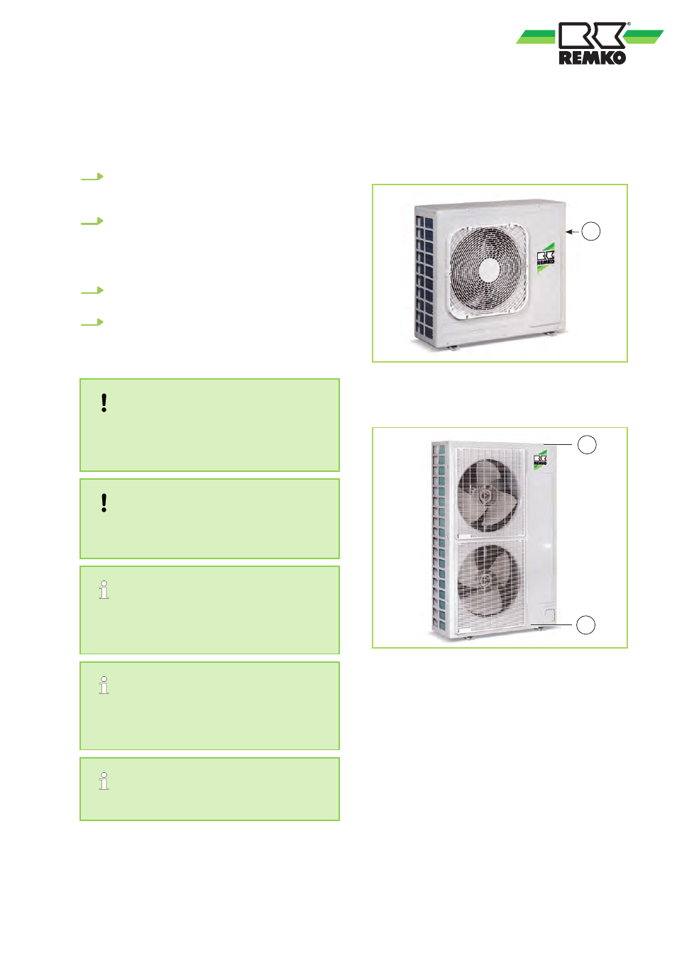
2.6
Electrical connection -
outdoor unit
n
In order to establish the electrical connections,
the right-hand cover panel must be removed
(after undoing the screws).
1
Fig. 6: Series WKF 120 Duo - Removing the
plastic cover by undoing the screw
1: Screw
1
1
Fig. 7: Series WKF 180 Duo - Removing the cover
panel by undoing the screws
1: Screw
n
Electrical protection for the system is imple-
mented in accordance with the information in
the technical data. Observe the required con-
ductor cross-sections!
n
All cables must be connected with the correct
polarity and strain relief.
n
Follow the connection schematic and the circuit
diagram.
n
The two-wire control line is to be connected to
terminals F1, F2 and the earth terminal.
n
When connecting the control line, make sure
that polarity is correct.
13