Wiring diagram fan motor – REMKO VRS 20 User Manual
Page 21
21
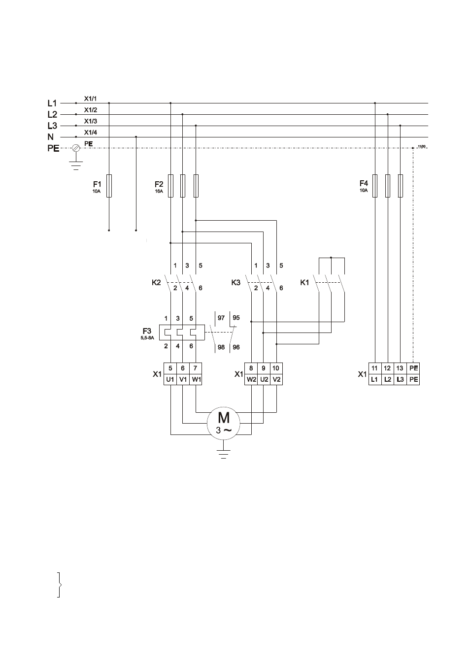
Fan motor connection 400 V / 3~
Burner motor connection ( 3~ )
Connection to the
thermal overcurrent relay
on the burner motor
Control voltage
Burner 400 V
An easily accessible emergency switch must be at-
tached in the setup room, but not close to hazardous
areas.
This switch must be protected from damage and un-
authorised use!
The electrical connections should only be made by
authorised personnel.
We reserve the right to make modifications in dimensions and construction in the interests of technical progress.
F1 Control fuse
F2 Fuse block (fan motor)
F3 Thermal overcurrent relay (fan motor)
F4 Fuse block burner motor (optional)
H2 Malfunction lamp (burner)
H3 Operating lamp (burner)
H4 Malfunction lamp (overheating)
H5 Operating lamp (fan)
H6 Malfunction lamp (fan)
KB
REMKO triple combination control
K1M
K2M Contactor for
∆
/ Y
switch
K3M
M Fan motor
RT Room thermostat
S1 Operating switchC
STB Safety temperature limiter
TR
Temperature control thermostat
TW Temperature monitor
Wiring Diagram Fan Motor