Wiring diagram 230 v – REMKO VRS 20 User Manual
Page 18
18
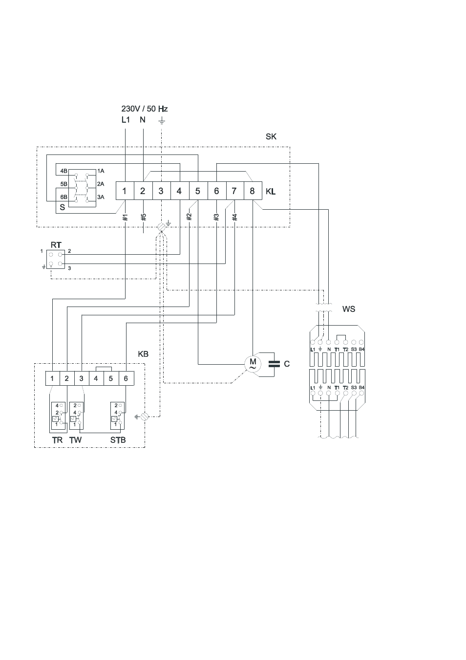
Wiring Diagram 230 V
Fan motor: 230 V / 1~
Burner motor: 230 V / 1~
An easily accessible emergency switch must be at-
tached in the setup room, but not close to hazardous
areas.
This switch must be protected from damage and un-
authorised use!
The electrical connections should only be made by
authorised personnel.
We reserve the right to make modifications in dimensions and construction in the interests of technical progress.
C Capacitor
KB REMKO Triple Combination Control
KL Terminal strip in the control box
M Fan motor
RT Thermostat plug
S Operating switch
SK Control box
STB Safety temperature limiter
TR Temperature control thermostat
TW Temperature monitor
WS Wieland plug
(Only for factory-installed burner
)
Wieland plug from
the control box
Wieland socket
from the burner
blue
black
black 1
black 2
black 4
black 3
brown
blue
- PWL H (24 pages)
- CLK 150 (20 pages)
- ELT 2-1 (12 pages)
- CLK 170-RV (24 pages)
- DZH 90-2 (20 pages)
- ELT 9 (12 pages)
- ELT 18 S V.2 (12 pages)
- ELT 9-6 (12 pages)
- EST (8 pages)
- PGM 60 (16 pages)
- PGM 12 (12 pages)
- HTL 400 (20 pages)
- PGT 100 (20 pages)
- ATR-3 (16 pages)
- ATR-4 (16 pages)
- SLV11-88-2 (16 pages)
- PWW Series (36 pages)
- GTF-5 (8 pages)
- VRS Series (36 pages)
- GSG-4 (8 pages)
- GPM 75 (44 pages)
- ATR-2 (8 pages)
- ASF 100 (16 pages)
- ETF 460 (20 pages)
- ETF 320 (20 pages)
- ETF 550 (20 pages)
- WKL 30 INOX (24 pages)
- SLN 80 (20 pages)
- RBW 300 PV-S (48 pages)
- HTS 260 CAMURA (76 pages)
- WKF 180 Duo S-line (64 pages)
- WKF-compact S-Line (96 pages)
- AMT 15 (16 pages)
- AMT 25 (16 pages)
- ETF 220 (16 pages)
- TX 3000 (8 pages)
- PG 50 (16 pages)
- TX 9000 (8 pages)
- CLK 20 (20 pages)
- AT 25 (16 pages)
- DZ 18 HD (16 pages)
- HTK 160 (20 pages)
- PG 12E (16 pages)
- PWL (24 pages)
- PWW 5000 (12 pages)