Safety device – REMKO VRS 25 INOX User Manual
Page 5
5
Operation
After switching on the unit by setting the operating
switch to „I” or “Heizen” (heating), the forced-air burner
turns on automatically.
For the 400 V model, the “burner“ operating light is illu-
minated on the control box for monitoring purposes. The
combustion chamber with heat-exchanger now heats up
until the target temperature is reached.
After the set target temperature is reached, the air sup-
ply fan switches on automatically. The “Fan” operating
light on the control box also lights up on the 400 V
model for monitoring purposes. Warm air is blown out.
Depending on how much heat is required, the process
described is repeated.
If heating mode is controlled via a room thermostat or
other temperature regulating device (operating switch
set to „I” or “Heizen” (heating), the units function fully-
automatically based on amount of heat required.
All of the unit functions are performed automatically and
monitored by the triple combination control and the
automatic burner relay (part of the forced-air burner).
After the device is switched off with the operating switch
or the room thermostat, the air supply fan runs for a cer-
tain amount of time to cool the combustion chamber
with heat-exchanger and then switches off. This proc-
ess can be repeated several times.
If the flame burns irregularly or goes out, the unit is
switched off by the automatic burner relay.
The automatic burner relay’s malfunction light as well as
the “Burner” malfunction light (the 400 V mode only) on
the control box light up. The unit may only be restarted
after the automatic burner relay has been manually re-
leased.
The safety temperature limiter (STB) interrupts opera-
tion of the unit or burner when extreme overheating oc-
curs or if the TW ceases functioning. The STB can only
be manually released after the unit has cooled.
For units in the 400 V series, the fan motor is also moni-
tored by a thermal overcurrent relay.
If the motor becomes overloaded, operation is inter-
rupted by the relay and the red malfunction lamp
“Ventilator” (fan) on the control box lights up. Release is
only possible after the control box has been opened.
G
Before releasing the overcurrent relay, the possible
causes of the malfunction must be investigated.
G
Never interrupt (except in emergency situations)
the power supply until the cool-down phase is
completely finished.
Our guarantee does not cover damages caused to
the unit by overheating.
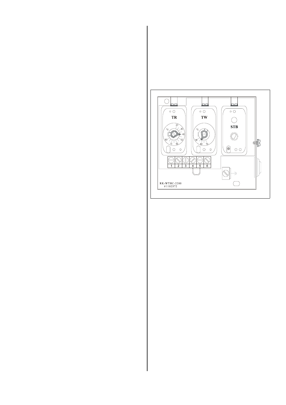
Safety Device
Triple combination control
The device has 3 safety functions:
à Fan control thermostat (TR)
à Temperature monitor (TW)
à Safety temperature limiter (STB)
The 3 functions of the triple combination control
1. Fan control thermostat (TR)
The fan control thermostat switches the circulating
air fan off and on. The switching point is set via the
temperature control thermostat “TR”.
Rated value approx. 40°C.
2. Temperature monitor (TW)
When the unit is in heating mode, the temperature
monitor limits both the temperature of the unit and
the air being blown out. The switching point is set via
the temperature control thermostat “TW”.
Rated value approx. 80 to 85°C.
3. Safety temperature limiter (STB)
The STB controls the temperature monitor.
The switching point is fixed.
The burner is prevented from being restarted if the
STB is activated. The reset button is operated from
outside.
G
Before the STB is released (to restart operation),
the reason the STB was activated must be deter-
mined.
Fig. Without housing cover