Wiring diagram 400 v y / ∆ fan motor – REMKO VRS 25 INOX User Manual
Page 21
21
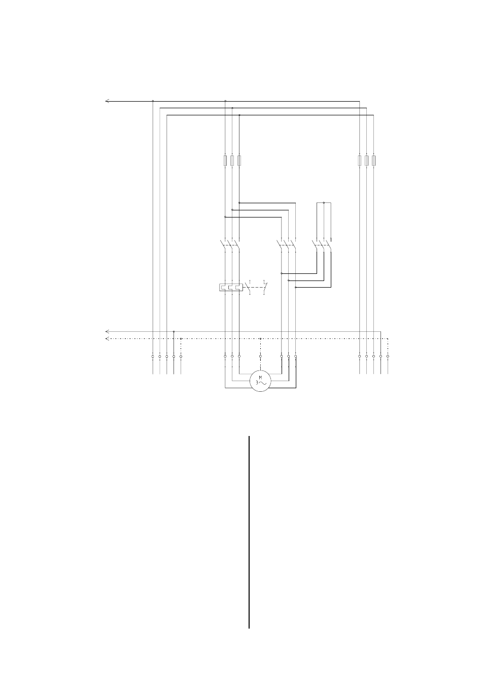
F1 Fuse block, fan motor
F2 Fuse block, burner motor (optional)
F3 Thermal overcurrent relay, fan motor
F4 Control fuse
H1 Malfunction lamp, fan
H2 Operating lamp, fan
H3 Operating lamp, burner
H4 Malfunction lamp, burner
KB REMKO triple combination control
K1 Contactor, power supply
K2 Contactor, delta connection
K3 Contactor, star connection
K4 Timing relay
M1 Fan motor
RT Room thermostat or regulator (optional)
Wiring Diagram 400 V Y / ∆ Fan motor
Fan motor: 400 V / 3~ (over 3,0 kW)
Burner motor: (400 V / 3~ optional)
P Running hour meter (optional)
S1 Operating switch
STB Safety temperature limiter
TR Fan control thermostat
TW Temperature monitor
X1 Terminal strip 1 in the control box
X2 Terminal strip 2 in the control box
L1
PE
L1 L2 L3 N
L1 L2 L3 N PE
U1
V1
W1
PE
W2
U2
V2
N
PE
X1
M1
F3
K1
K2
K3
F1
F2
1
2
3
4
PE
5
6
7
8
9
10
PE
11 12
13
14
PE
2
4
6
1
3
5
2
4
6
1
3
5
2
4
6
1
3
5
2
4
6
1
3
5
2
4
6
1
3
5
2
4
6
1
3
5
97
96
98
95
400V / 50 Hz / 3~ N PE
Fan motor
400V / 50 Hz / 3~ N PE
for optional
3~ burner motor
An easily accessible emergency switch must be at-
tached in the setup room, but not close to hazardous
areas.
This switch must be protected from damage and un-
authorised use!
G
The electrical connections should only be made by
authorised personnel.
We reserve the right to make modifications in dimensions and construction in the interests of technical progress.