Wiring diagram 230 v – REMKO VRS 25 INOX User Manual
Page 18
18
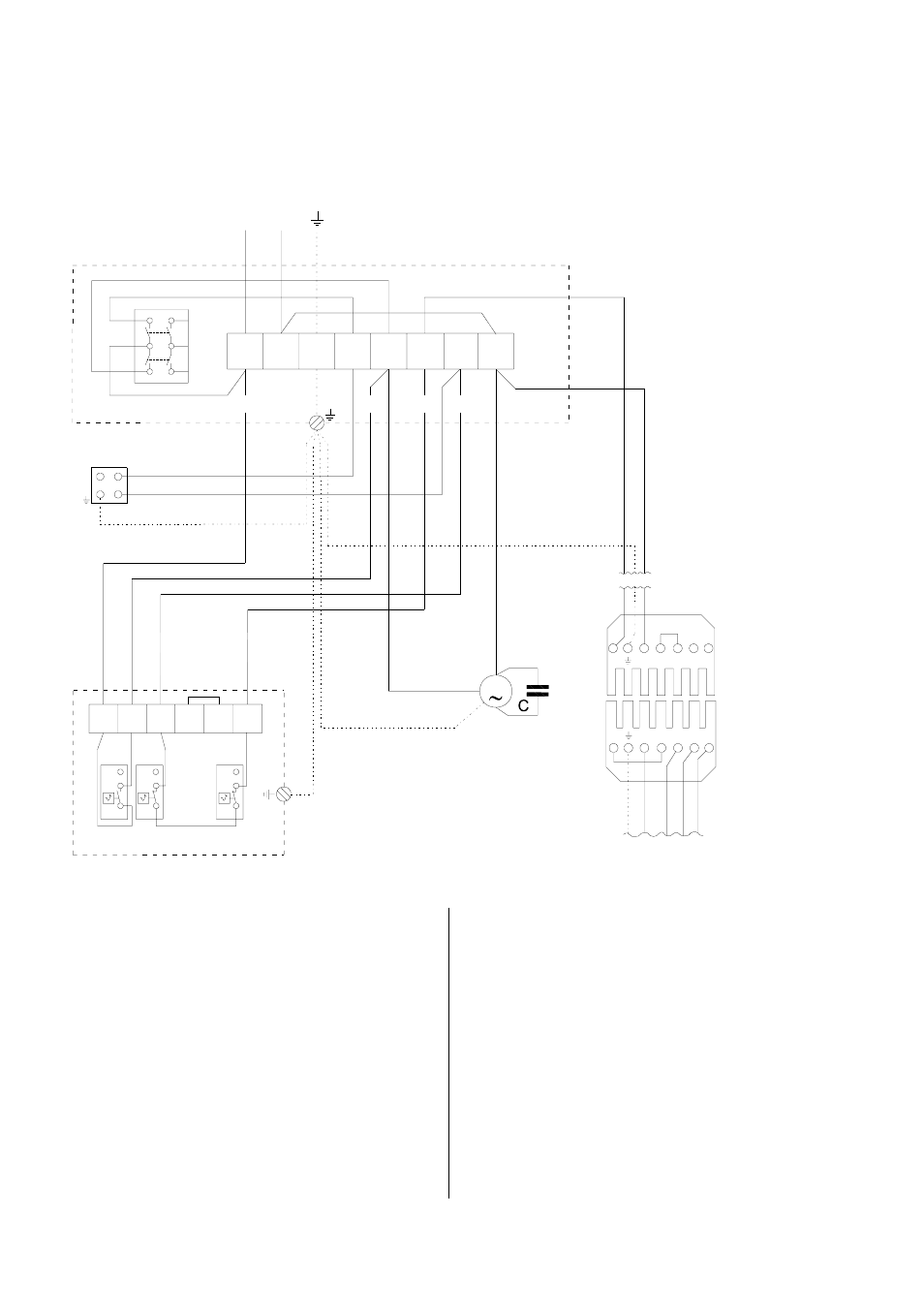
Wiring Diagram 230 V
Fan motor: 230 V / 1~
Burner motor: 230 V / 1~
Wieland socket
from the burner
Wieland plug
Included with pur-
chase of burner.
Burner cable
Prepared at the fac-
tory for connection to
the wieland socket
L1
N T1 T2 S3 B4
2
3
1
5B
2A
#2
#3
#4
#1
schwa
rz
blau
bl
a
u
br
a
un
L1
N T1 T2 S3 B4
1
4
2
1
4
2
1
1
4
2
schw
.1
schw
.2
schw
.4
schw
.3
M
4B
1A
6B
3A
1
2
3
4
5
6
7
8
2
3
4
5
6
L1
N
230V / 50 Hz
S
KL
SK
WS
RT
TR TW
STB
KB
bl
ue
bl
ac
k
bl
ac
k 1
bl
ac
k 2
bl
ac
k 4
bl
ac
k 3
brow
n
bl
ue
We reserve the right to make modifications in dimensions and construction in the interests of technical progress.
An easily accessible emergency switch must be at-
tached in the setup room, but not close to hazardous
areas.
This switch must be protected from damage and un-
authorised use!
G
The electrical connections should only be made by
authorised personnel.
C Capacitor
KB REMKO Triple Combination Control
KL Terminal strip in the control box
M Fan motor
RT Thermostat socket
S Operating switch
SK Control box
STB Safety temperature limiter
TR Fan control thermostat
TW Temperature monitor
WS Wieland plug
(Only for factory-installed burner
)