Electrical connection – REMKO PWW 5000 User Manual
Page 5
5
Connection to the heating system
Before connecting to the customer heating system, the
heating and pump capacity must be checked to ensure
that they meet the technical requirements of the respec-
tive unit.
The REMKO PWW unit should be connected via shut-
off valve, automatic dehumidifier and screw attach-
ments in the supply and return lines.
Draining in case of frost
It is not possible to statically drain the heat-exchanger
completely. The heat-exchanger can only be completely
drained when compressed air is used.
Drainage
Screws
Ventilation
Frost protection thermostat
Connecting the units
REMKO PWW 5000 models are equipped with axial
fans that have external rotary current motors for a volt-
age of 400 V / 3~ / 50 Hz. Switching the two speeds of
the rotary current motor is done with a Y /
∆ switch.
Integrated thermal contacts protect the motor.
They switch off the fan motor at a winding temperature
of 130 °C in connection with a suitable switching device
(accessory).
The rotary current motors are connected to the corre-
sponding switching units in accordance with the respec-
tive electrical wiring diagrams.
The corresponding power fuse in the line to the switch-
ing unit must be installed by the customer in line with
the relevant regulations.
The connections in the terminal box of the unit must be
connected to the corresponding switching unit
(accessory).
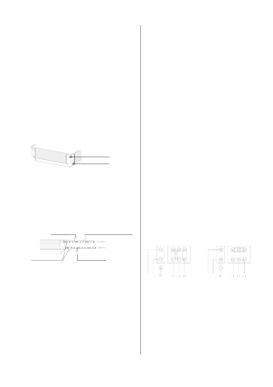
Connecting the fan motor
Motor with 2 speeds, Y/
∆ switch and thermal contacts.
High-speed
∆ switch
When the fan is idle, the heating medium supply
must be interrupted.
*
◊ The units operate on the principle of counter-current:
The water (supply line) usually comes in at the bottom,
the water (return line) usually goes out at the top
◊ Once assembled, the heat-exchanger must be care-
fully ventilated because air pockets in the register
can reduce unit performance.
Important information about frost protection!
To prevent frost damage, a frost protection mechanism
must be attached for temperatures below 0 °C.
There may not be any water in the heat-exchanger for
systems taken out of operation in rooms susceptible to
frost. The remaining water must be blown out with com-
pressed air.
If this is not possible, the heating medium (water) must
be mixed with a suitable anti-freeze.
Restriction of guarantee!
Non-compliance with the relative legal requirements,
operating instructions and unit-specific wiring diagrams
can lead to malfunctions that cause damage.
In cases of non-compliance, the guarantee becomes null
and void
!
Low speed Y switch
Connecting several units
If necessary, several units (even of different sizes) can
be operated at the same time via a switching unit
(accessory).
The overall capacity of the connected units may not,
however, exceed the maximum electrical capacity of the
corresponding switching unit.
For thermal motor protection, the thermal contacts of all
motors are to be connected in a row. Follow the sepa-
rate wiring diagrams.
There can never be more than one external regulating
mechanism per switching unit connected at a single time!
Outgoing water
All connections 1“ inner thread
Incoming water
Electrical Connection
The requirements of the local energy supply company
as well as installation requirements specific for each
unit must be observed.
The electrical connection may only be made by
trained and authorised personnel.
*
No guarantee claims can be made for frost damage
on the heat-exchanger!
*
When connecting the screw attachments of the
heating medium connection, a suitable tool should
be used to apply counter-pressure to prevent dam-
age caused by turning the connection lines.
*